Catalyst regeneration scorching method and device

A technology for catalysts and catalyst beds, applied in catalyst regeneration/reactivation, chemical instruments and methods, physical/chemical process catalysts, etc., can solve problems affecting catalyst life and hydrothermal stability of catalysts, etc.

Pending Publication Date: 2021-11-02
BC P INC CHINA NAT PETROLEUM CORP +1
View PDF4 Cites 0 Cited by
  • Summary
  • Abstract
  • Description
  • Claims
  • Application Information

AI Technical Summary

Problems solved by technology

[0004] However, in related technologies, the charred gas circulated back to the charred bed has a certain humidity, which is wet charred gas, and wet charred gas will affect the hydrothermal stability of the catalyst, thereby affecting the life of the catalyst

Method used


Image

  • Catalyst regeneration scorching method and device
  • Catalyst regeneration scorching method and device
  • Catalyst regeneration scorching method and device

Examples


Embodiment Construction

[0065] In order to make the technical solutions and advantages of the present application clearer, the implementation manners of the present application will be further described in detail below.

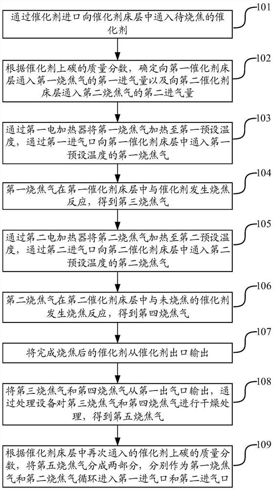
[0066] The embodiment of the present application provides a catalyst regeneration coking method, see figure 1 , the method includes:

[0067] Step 101: Pass the catalyst to be burnt into the catalyst bed through the catalyst inlet.

[0068] The catalyst to be burnt is the catalyst with coke on the surface, the catalyst is located in the catalyst bed, and the catalyst in the catalyst bed moves down slowly by its own gravity.

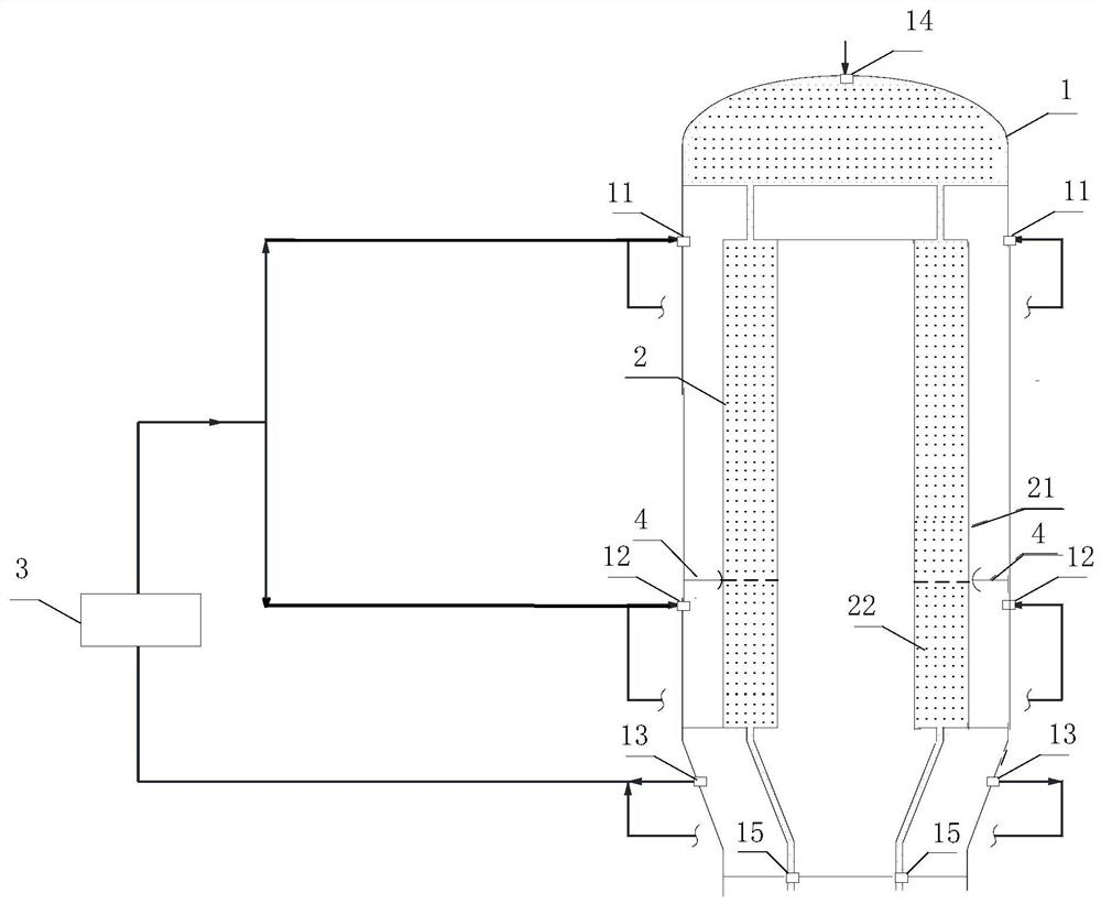
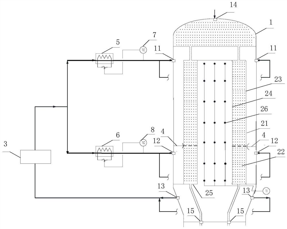
[0069] The catalyst bed includes a first catalyst bed and a second catalyst bed, which are continuous catalyst beds. And the catalyst bed layer is a radial moving bed, including a gas distribution pipe, a gas collection pipe and a supporting bed, an annular chamber is formed between the gas distribution pipe and the gas collection pipe, and the catalyst is lo...


PUM


Abstract

The invention discloses a catalyst regeneration scorching method and device, and belongs to the technical field of catalyst regeneration. According to the method, a section of charring bed layer is divided into two charring areas through a partition plate, charring gas is introduced into the corresponding charring areas through a first gas inlet and a second gas inlet, and one-section charring and multi-section gas inlet are achieved. Moreover, the introduced scorching gas is dry gas, so that the hydrothermal stability of the catalyst is maintained while the catalyst is scorched, and the service life of the catalyst is prolonged. Besides, the air inlet amount of the coke-burning gas can be adjusted according to the mass fraction of carbon on the catalyst, so that the coke-burning effect is ensured.

Description

technical field [0001] The present application relates to the technical field of catalyst regeneration. In particular, it relates to a catalyst regeneration coking method and device. Background technique [0002] During the process of catalytic reforming or alkane dehydrogenation, coke will be formed on the surface of the catalyst, which will lead to the gradual deactivation of the catalyst during use and the decrease of activity. Therefore, regeneration of the catalyst needs to be achieved. [0003] In the related technology, the coke gas is mainly introduced into the coke bed, which includes the catalyst bed, and the catalyst with coke on the surface is located in the catalyst bed, and the coke gas is introduced into the catalyst bed, and the coke gas is passed through the coke bed. The gas is used to burn the catalyst in the catalyst bed, and after the burning is completed, the burnt gas is recycled back to the burnt area, so as to realize the regeneration of the cataly...

Claims


Application Information

Patent Timeline
IPC IPC(8): B01J38/14B01J38/02
CPCB01J38/14B01J38/02
Inventor 边建东王志刚刘廷斌魏治中韩晓琳任建生接瑜刘方吴占永赖文川张鹏于新文许佳崔佳李俊奎
Owner BC P INC CHINA NAT PETROLEUM CORP
Why Eureka
Try Eureka