Impeller pump

A vane pump and vane technology, applied in the field of spring-supported double eccentric vane pump, can solve the problems of high cost and easy wear of single semi-circular key connection

Active Publication Date: 2015-01-14
BOSCH AUTOMOTIVE DIESEL SYST
View PDF11 Cites 7 Cited by
  • Summary
  • Abstract
  • Description
  • Claims
  • Application Information

AI Technical Summary

Problems solved by technology

The spline connection is strong but expensive, and ...

Method used


Image

  • Impeller pump

Examples


Embodiment Construction

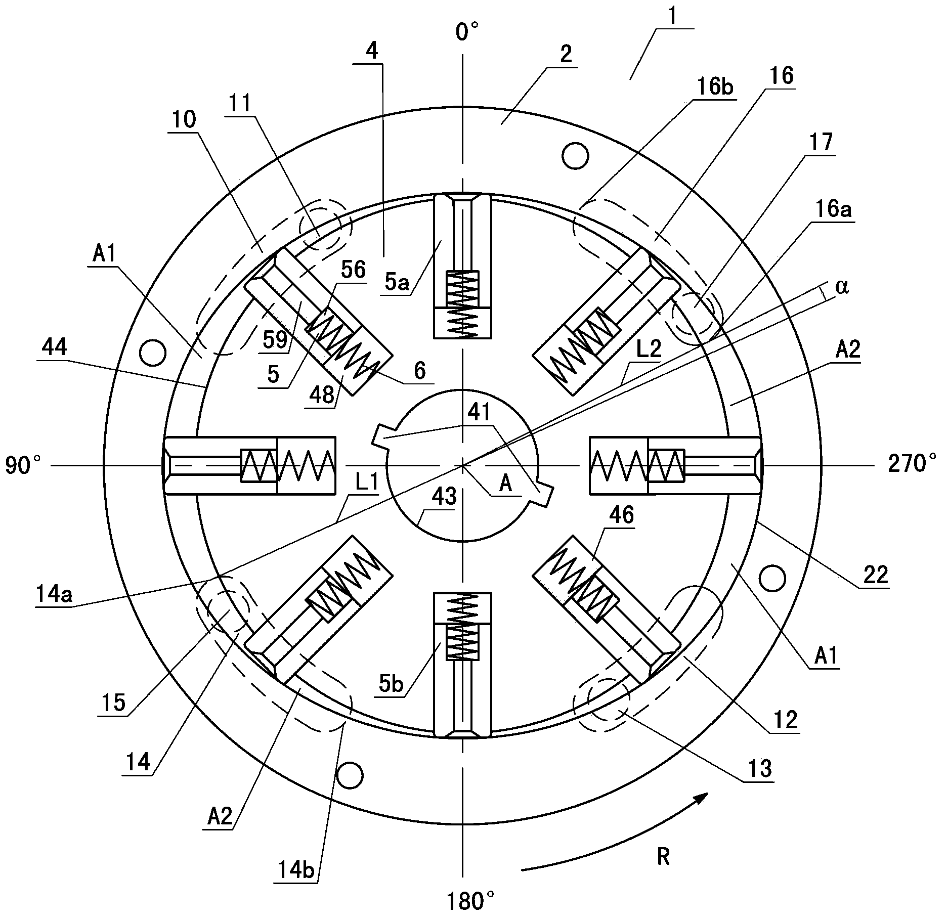
[0026] The principle according to the invention is applicable to eccentric vane pumps, especially multi-eccentric vane pumps. It will be specifically described with reference to the double eccentric vane pump in the accompanying drawings, which can be used as a pre-supply pump of a high-pressure fuel pump for pressurizing fuel in a fuel injection device of a vehicle. Obviously, the application of eccentric vane pumps is not limited to this.

[0027] refer to figure 1 , which shows a cross-sectional view of the vane pump 1, the double eccentric vane pump 1 according to the present invention includes a stator 2 and a rotor 4 arranged in the stator 2, the rotor 4 defines the axis of rotation, in figure 1 Indicated with reference sign A. The vane pump 1 also includes two end covers located at opposite ends of the stator 2 in the direction of the rotation axis A of the rotor 4 . Optionally, one of the two end covers can be integrally formed with the stator 2 . The end cover of ...


PUM


Abstract

The invention provides an eccentric impeller pump. The eccentric impeller pump comprises 1, a stator which comprises an inner wall for spacing an inner space, 2, a rotor which is arranged in the inner space, can space a rotation axis and comprises an outer wall forming a gap with the inner wall of the stator, wherein the gap comprises multiple sample quasi-crescent gap parts uniformly distributed at intervals along a peripheral direction around the rotation axis, 3, two end covers, 4, multiple blades which are respectively arranged in corresponding blade slots extending from the outer wall of the rotor to inside and are retractable, and 5, multiple oil inlet tanks and multiple oil outlet tanks which are arranged on the end covers, wherein each one of the gap parts is corresponding to one oil inlet tank and one oil outlet tank, at least one of the oil inlet tanks and other oil inlet tanks are non-uniformly arranged at intervals around the center of the rotation axis of the rotor and at least one of the oil outlet tanks and other oil outlet tanks are non-uniformly arranged at intervals.

Description

technical field [0001] The present invention relates to the field of multiple eccentric vane pumps, and more particularly to spring-loaded double eccentric vane pumps with asymmetrically arranged oil inlet and outlet grooves. Background technique [0002] Vane pumps are widely used in various equipment for supplying hydraulic fluid in a certain pressure range and a certain flow range into the equipment. For example, a vane pump is used as a pre-supply pump for a high-pressure fuel pump of a vehicle. [0003] A conventional vane pump includes a stationary stator and a rotatable rotor housed in an interior space defined by the stator. Vane slots are formed on the outer wall of the rotor, and vanes are disposed in the vane slots and extend substantially radially outward with respect to the rotational axis of the rotor. The vanes are radially extendable and retractable within the vane slots. Every two adjacent blades, and the inner wall of the stator and the outer wall of the...

Claims


Application Information

Patent Timeline
IPC IPC(8): F04C2/344F02M59/00
CPCF04C2/3446F01C21/0845F04C15/06F04C2210/1044
Inventor S·克劳斯
Owner BOSCH AUTOMOTIVE DIESEL SYST
Why Eureka
Try Eureka