Connector and electronic equipment

A technology for electronic equipment and connectors, applied in the field of electronics, can solve the problems of light weight of the rotating shaft, and achieve the effect of light weight, light weight and light weight

Active Publication Date: 2015-01-14
LENOVO (BEIJING) CO LTD
View PDF6 Cites 8 Cited by
  • Summary
  • Abstract
  • Description
  • Claims
  • Application Information

AI Technical Summary

Problems solved by technology

[0005] The embodiment of the present application provides a connecting body and electronic equipment to solve the technical problem that the n

Method used


Image

  • Connector and electronic equipment
  • Connector and electronic equipment
  • Connector and electronic equipment

Examples


Example Embodiment

[0039] The embodiment of the present application solves the technical problem of the notebook computer in the prior art that it cannot meet the requirements for torque of the rotating shaft and the demand for light weight of the rotating shaft by providing a connecting body and an electronic device.

[0040] The technical solution in the embodiments of the present application is to solve the above-mentioned problems, and the general idea is as follows:
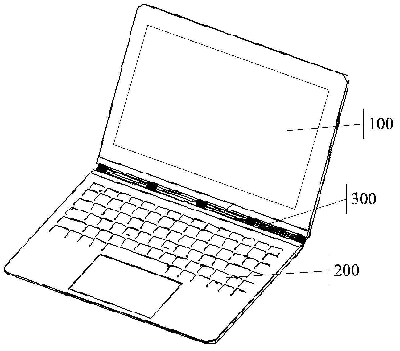
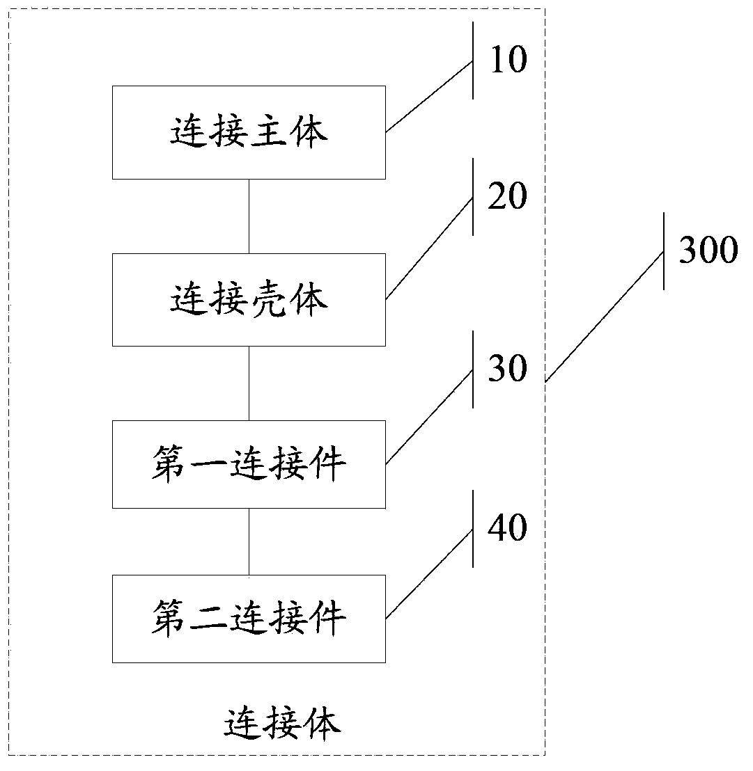
[0041] Provided is a connecting body applied to an electronic device, the connecting body is used to connect a first body and a second body of the electronic device, the connecting body includes:

[0042] The connecting body is made of a first material with a first specific gravity;

[0043] The connecting shell is made of a second material with a second specific gravity. The connecting shell is arranged on the outer surface of the connecting body and covers the whole or part of the outer surface of the connecting body, wherein the fir...


PUM


Abstract

The invention discloses a connector and electronic equipment. The connector is used for connecting a first main body and a second main body in the electronic equipment. The connector comprises a connection main body which is prepared from a first material with a first specific gravity rate, a connection housing which is prepared from a second material with a second specific gravity rate and is arranged on and covers all or a part of the outer surface of the connection main body, wherein the second specific gravity rate is less than the first specific gravity rate, a first connection member which is arranged on the connection main body, and a second connection member which is arranged on the connection main body, wherein while the first main body around the connection body rotates around the second main body from a first position to a second position, a first shape of the connector corresponding to a first position is changed into a second shape of the connector corresponding to a second position and the first shape is different from the second shape.

Description

technical field [0001] The present application relates to the field of electronic technology, in particular to a connector and an electronic device. Background technique [0002] With the rapid development of electronic technology, the functions of various electronic devices are becoming more and more abundant, and more and more humanized, so that users can have a better experience in the process of using electronic devices. Use requirements, some notebook computers now pursue the function of large-angle flip, or the display and keyboard base can be separated, these requirements put forward higher requirements for the design of the connection shaft of the notebook computer; [0003] However, in the process of realizing the technical solution of the invention in the embodiment of the present application, the inventor of the present application found that the above-mentioned technology has at least the following technical problems: [0004] Existing notebook computers use ste...

Claims


Application Information

Patent Timeline
IPC IPC(8): F16C11/04G06F1/16
Inventor 田平
Owner LENOVO (BEIJING) CO LTD
Why Eureka
Try Eureka