

Lens and illuminating device comprising same
A lighting device and lens technology, which is applied to lighting devices, components of lighting devices, lighting and heating equipment, etc., can solve the problem of high cost, and achieve the effect of easy processing and good economy
- Summary
- Abstract
- Description
- Claims
- Application Information
AI Technical Summary
Problems solved by technology
Method used
Image

Examples
Embodiment Construction
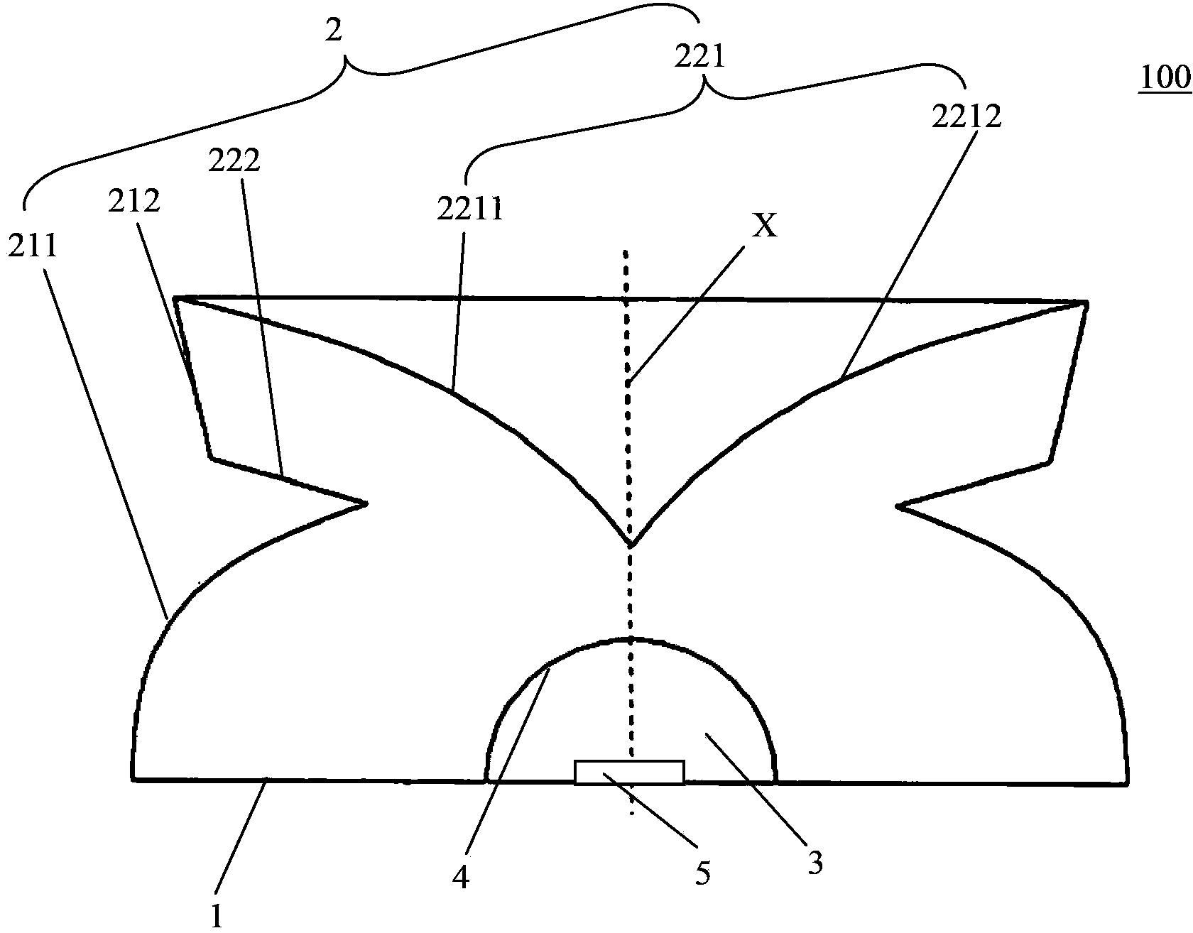
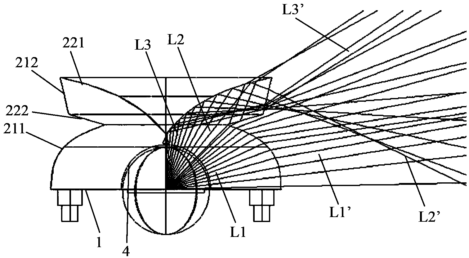
[0025] Such as figure 1 with figure 2 as shown, figure 1 is a cross-sectional view of a lens 100 according to an embodiment of the present invention, figure 2 is based on figure 2 is an optical path diagram of a lens according to an embodiment of the present invention. The lens 100 has a bottom surface 1 , a surface 2 , and a central axis X perpendicular to the bottom surface 1 , and also has a cross section perpendicular to the central axis X. On the bottom surface 1 of the lens 100, a recessed area 3 is raised, such area is used to accommodate a light source which can be implemented as an LED chip, so that, by virtue of the surface of the recessed area 3 as the incident surface 4, the light from the light source can be injected into the lens. Wherein, the recessed area 3 can be designed to have a hemispherical, semi-elliptical or conical contour, but not limited to these forms of contours, other contours that can achieve similar effects can be designed as the contour...
PUM
 Abstract
Description
Claims
Application Information