
Fuse for electrical machine

A technology of electrical machinery and fuses, applied in the field of electric power, can solve the problems of inability to use photovoltaic products, inconvenient installation and disassembly, and inconvenient disassembly, and achieve the effects of increased ventilation performance, simple structure, and long service life

Inactive Publication Date: 2015-01-14
李亚林
View PDF4 Cites 2 Cited by
  • Summary
  • Abstract
  • Description
  • Claims
  • Application Information

AI Technical Summary

Problems solved by technology

In the existing fuse, the copper wire is directly connected to the end cover and the liner. Since the end cover and the liner are both inconvenient to disassemble, the connection between the copper wire, the end cover and the liner is difficult during installation and disassembly. The method is very inconvenient, which brings inconvenience to the construction. In addition, the existing fuse, the melt is made of copper, and photovoltaic products cannot be used.

Method used


Image

  • Fuse for electrical machine
  • Fuse for electrical machine
  • Fuse for electrical machine

Examples


Embodiment Construction

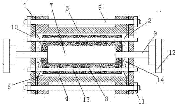
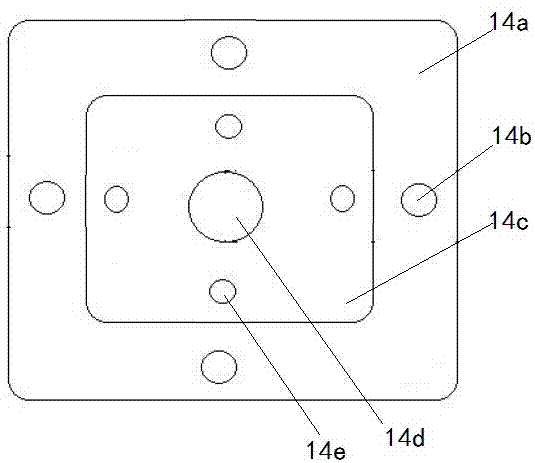
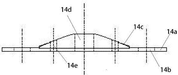
[0015] refer to figure 1 The fuse for electrical machinery shown is characterized in that it includes a left end cover 1, a right end cover 2, a housing 3 and a fuse tube 4, the left end cover 1 is installed on the left side of the housing 3, and the right end cover 2 is installed on the housing 3, the left end cover 1, the shell 3 and the right end cover 2 are provided with a screw 5, and the screw 5 is set through the left end cover 1, the shell 3 and the right end cover 2 in turn; the left end cover 1, the shell 3 and the right end A cavity 6 is formed between the covers 2, the melting tube 4 is installed in the cavity 6, and the melting tube 4 is provided with a melt 7; the left end cover 1 and the right end cover 2 are provided with terminal posts 9, The terminal post 9 is provided with ceramic insulation and heat sink 12, and the terminal post 9 is connected to the fusion pipe 4; the left end cover 1 and the right end cover 2 are provided with ventilation holes 10, and t...


PUM


Abstract

The invention discloses a fuse for an electrical machine. The fuse comprises a left end cover, a right end cover, a shell and a fusion tube. The left end cover is mounted on the left side of the shell. The right end cover is mounted on the right side of the shell. A screw is arranged on the left end cover, the shell and the right end cover and penetrates through the left end cover, the shell and the right end cover in sequence. A cavity is formed among the left end cover, the shell and the right end cover. The fusion tube is mounted in the cavity. A fuse body is arranged in the fusion tube. The left end cover and the right end cover are both provided with binding posts. Each binding post is provided with ceramic insulation and cooling fins. The binding posts are both connected with the fusion tube. The left end cover and the right end cover are both provided with vent holes. Ceramic cooling sticks penetrating through the fusion tube are arranged in the vent holes. The left end cover, the shell and the right end cover are matched and fixed through the screw and a nut in sequence.

Description

technical field [0001] The invention relates to a fuse for electrical machinery and belongs to the field of electric power. Background technique [0002] The fuse is based on the fact that after the current exceeds the specified value for a period of time, the heat generated by itself melts the melt, thereby disconnecting the circuit; a current protector made by using this principle. Fuses are widely used in high and low voltage power distribution systems and control systems, as well as electrical equipment, as short circuit and overcurrent protectors, and are one of the most commonly used protection devices. A fuse is a type of overcurrent protector. The fuse is mainly composed of melt, fuse tube and external filler. When in use, connect the fuse in series in the protected circuit. When the current of the protected circuit exceeds the specified value, and after a certain period of time, the heat generated by the melt itself will fuse the fuse and disconnect the circuit, t...

Claims


Application Information

Patent Timeline
IPC IPC(8): H01H85/175H01H85/47H01H85/06H01H85/18
CPCH01H85/0013H01H85/06H01H85/175H01H85/18H01H85/47
Inventor 龙文凯
Owner 李亚林
Learn More