Water cyclone dust removal system

A technology of cyclone dust removal and air duct, which is applied in the direction of dispersed particle separation, chemical instruments and methods, and the use of liquid separation agents, etc., can solve the problems of unsuitable for general application, large footprint, high cost, etc., and achieve the best dust removal and purification effect, Improved dust removal efficiency and low cost

Active Publication Date: 2015-01-21
龙伍洋
View PDF5 Cites 7 Cited by
  • Summary
  • Abstract
  • Description
  • Claims
  • Application Information

AI Technical Summary

Problems solved by technology

However, the dust removal methods listed above all have their own defects, either the dust removal effect is not ideal, the efficiency is low, or the cost is high and the floor area is too large, which is not suitable for general application.
In addition, in the

Method used


Image

  • Water cyclone dust removal system
  • Water cyclone dust removal system
  • Water cyclone dust removal system

Examples


Embodiment 1

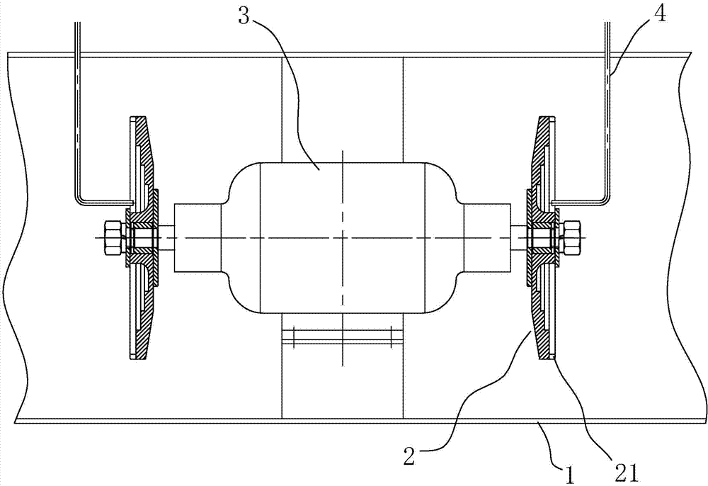
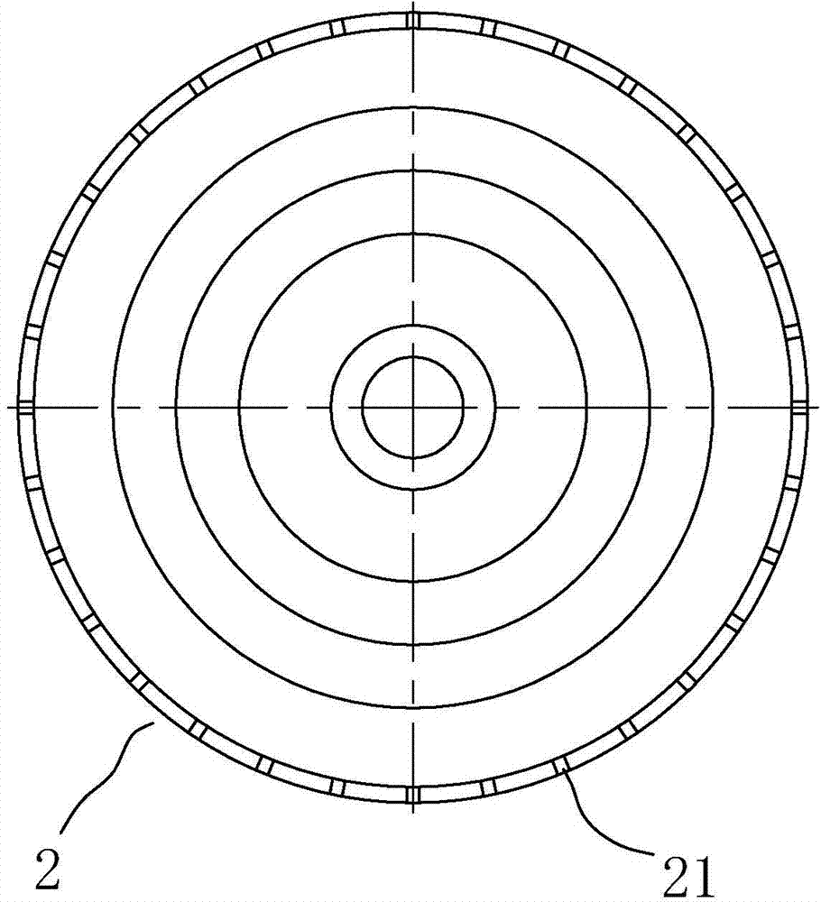
[0015] Embodiment 1: refer to Figure 1 ~ Figure 2 , water cyclone dust removal system, including: dust removal air duct 1, which is provided with a drain port; water throwing tray 2, which is disc-shaped, and one of the disks is concaved to the center to form an arc surface, and the disk is used as a water throwing surface, and the water throwing tray 2. It is arranged in the dust removal air duct 1, and the water rejection surface faces the inlet or outlet direction of the dust removal air duct 1, and the periphery of the water rejection surface stands up to form a vertical wall; There are a plurality of flow diversion tanks 21, which are evenly distributed on the vertical wall; a power device, which is connected with the water throwing tray 2 and can drive it to rotate; a water spraying device, which can supply water to the water throwing surface. The waterproof motor 3 can be fixed conveniently by setting a bracket in the dust removal air duct 1 . The drain can be special...

Embodiment 2

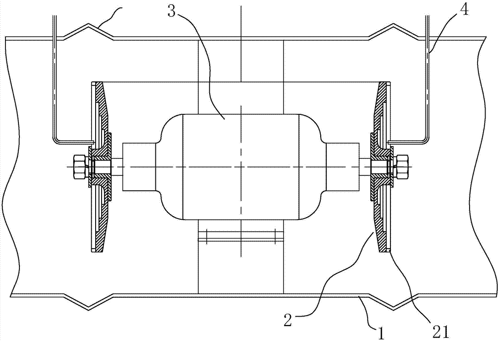
[0022] Embodiment 2: refer to figure 2 and image 3 In the case of the same basic structure as that of Embodiment 1, in the radial circumferential space of the water throwing pan 2, there are provided for meeting the impact of the water flow thrown out from the splitter groove 21 and making the water flow bounce back, Sputtering into the inclined slope structure of the space in front of the water jet. Specifically, the dust removal air duct 1 has at least one section of an inner wall that is "V"-shaped in axial cross-section, with the pointed corner of the "V" facing outward, and this section of the inner wall serves as the inclined-angle slope structure. Obviously, when the water ring blade hits the V-shaped inner wall at high speed, due to the guidance of the inclined surface, the water mist formed by the broken water droplets will bounce back to the water surface. On the one hand, the water sent by the water pipe per unit time can be fully recycled. On the other hand, th...


PUM


Abstract

The invention discloses a water cyclone dust removal system, which includes: a dust removal air pipe, which is provided with a drainage port; discoid water throwing discs, which are disposed in the dust removal air pipe, with one disc face of each disc wholly sinking to the center to form a cambered surface, and serving as a water throwing surface that is toward the inlet or outlet direction of the dust removal air pipe and has erected periphery to form a vertical wall; a plurality of shunting grooves grooved in the radial direction of the water throwing discs and uniformly distributed on the vertical wall; a waterproof motor, which is connected to the water throwing discs and can drive the water throwing discs to rotate; and water spraying equipment, which can provide water to the water throwing surface. Under high speed rotation of the water throwing discs, water on the water throwing surfaces can be spread to diverge and is thrown outward from the shunting grooves to form water ring blades and water mist areas. And dust in dusty gas is humidified, adsorbed into water, and then drained through the drainage port. With the characteristics of simple structure and low cost, the water cyclone dust removal system can be widely used in various occasions needing dust removal and purification on gas.

Description

technical field [0001] The invention relates to an industrial dust removal equipment. Background technique [0002] Many industrial production activities will lead to the generation of dust (the dust in this article includes various solid particles, oil droplets and other fine floating objects), so ceramic processing factories, stone factories, power plants, etc. need to set up dust removal equipment to meet environmental protection requirements. Production requirements. Traditional dust removal methods include dry dust removal and wet dust removal. Dry dust removal uses electrostatic adsorption, slaked lime adsorption, and multi-stage series membrane filtration to remove dust. In the solution, the dust is washed down and the gas is purified. However, the dust removal methods listed above all have their own defects, either the dust removal effect is not ideal, the efficiency is low, or the cost is high and the floor area is too large, which is not suitable for general appl...

Claims


Application Information

Patent Timeline
IPC IPC(8): B01D47/00
CPCB01D47/00
Inventor 龙其瑞龙伍洋黄军蔡永邦黄晓军李立延董文龙
Owner 龙伍洋
Why Eureka
Try Eureka