Centering clamp

A technology of centering fixture and clamping body, applied in the field of tooling fixture, can solve the problems of inability to meet the machining accuracy, inability to center the workpiece, poor centering accuracy, etc., and achieve convenient and quick pressure regulation, high centering accuracy and simple structure. Effect

Active Publication Date: 2015-01-21
CHONGQING CITY JIANGJIN DISTRICT JINXING MACHINERY
View PDF5 Cites 0 Cited by
  • Summary
  • Abstract
  • Description
  • Claims
  • Application Information

AI Technical Summary

Problems solved by technology

Due to the gap fit between the polished rod and the center hole of the workpiece, the workpiece cannot be centered effectively, and the centering accuracy is poor, resulting in the eccentricity of the outer cone after processing, which cannot meet the processing accuracy requirements.

Method used


Image

  • Centering clamp

Examples


Embodiment Construction

[0011] Below in conjunction with accompanying drawing and embodiment the present invention will be further described:

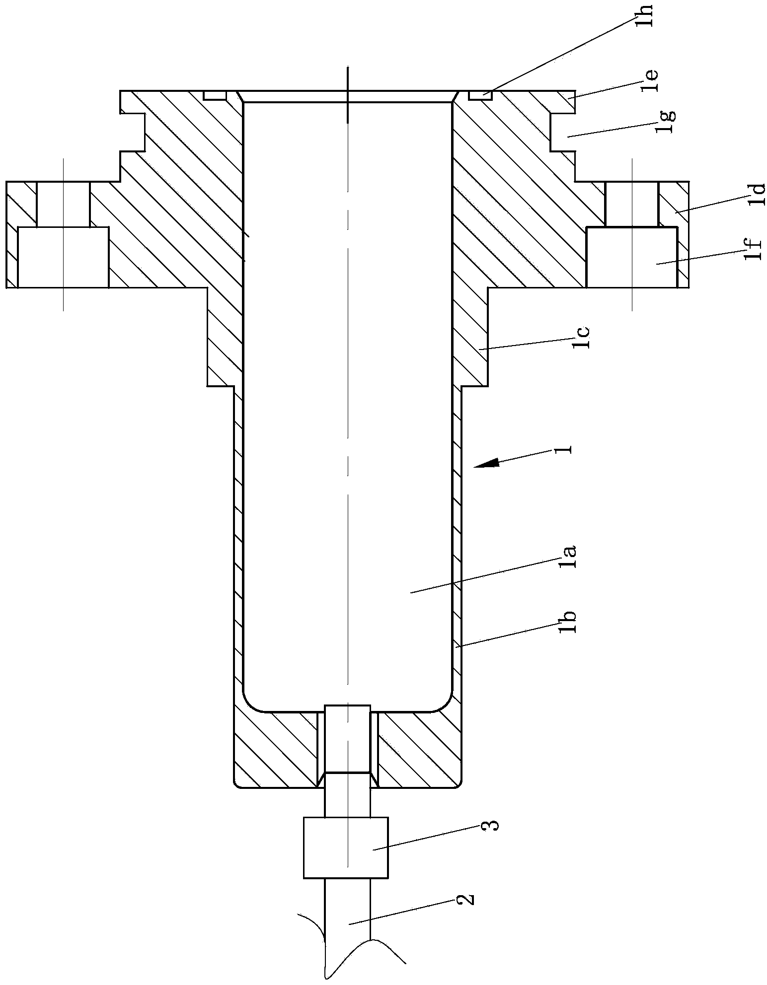
[0012] like figure 1 As shown, a centering fixture is mainly composed of a clamp body 1 , a pressure relief pipe 2 and a pressure relief valve 3 . Wherein, the material of clamp body 1 is spring steel, and the central hole 1a of this clamp body 1 is a two-section combination hole, and is formed by connecting the threaded hole section on the left and the oil injection hole section on the right, and the diameter of the oil injection hole section is larger than The diameter of the threaded hole segment. The oil inlet end of the pressure relief pipe 2 is connected to the threaded hole section of the central hole 1a of the clamp body 1, a pressure relief valve 3 is installed on the pressure relief pipe, and a hydraulic pump may be provided at the oil outlet end of the pressure relief pipe 2 connected.

[0013] The clamp body 1 is a four-stage stepped shaft stru...


PUM


Abstract

The invention discloses a centering clamp. A clamp body is made of spring steel. A center hole of the clamp body is a two-section-type combining hole and is formed by a thread hole section on the left and an oil injection hole section on the right in a connecting mode. The diameter of the oil injection hole section is larger that the diameter of the thread hole section. An oil inlet end of a pressure relief pipe is connected to the thread hole section of the center hole of the clamp body. A pressure relief valve is arranged on the pressure relief pipe. The clamp body is of a four-section type stepped shaft structure which comprises a first cylinder section, a second cylinder section, a third cylinder section and a fourth cylinder section from left to right in sequence. The length of the first cylinder section is 1 / 2-2 / 3 of the length of the clamp body. The position of the first cylinder section corresponds to the thread hole section of the center hole of the clamp body and the left portion of the oil injection hole section. At least three sinking table holes are evenly distributed in the periphery direction of the third cylinder section of the clamp body and are formed in the axial direction of the clamp body, and the sinking table holes become small from left to right. A workpiece can be subjected to centering effectively, centering accuracy is high, and pressure adjusting is convenient and quick.

Description

technical field [0001] The invention belongs to the field of tooling fixtures, in particular to a centering fixture. Background technique [0002] In the processing of the outer bevel or tooth shape of the gear, the workpiece needs to be centered first. At present, the polished rod is generally used to center the workpiece. Since there is a clearance fit between the polished rod and the center hole of the workpiece, the workpiece cannot be centered effectively, and the centering accuracy is poor, resulting in the eccentricity of the processed outer cone, which cannot meet the processing accuracy requirements. Contents of the invention [0003] The technical problem to be solved by the present invention is to provide a centering fixture with high centering precision. [0004] The technical scheme of the present invention is as follows: a centering clamp is characterized in that: it comprises a clamp body (1) and a pressure relief pipe (2), wherein the material of the clamp...

Claims


Application Information

Patent Timeline
IPC IPC(8): B23F23/06B23Q3/12
Inventor 段含辉
Owner CHONGQING CITY JIANGJIN DISTRICT JINXING MACHINERY
Why Eureka
Try Eureka