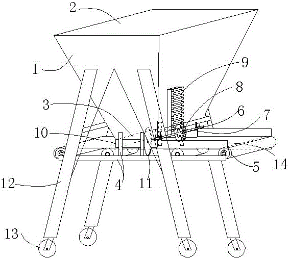
A crushing conveying device
A conveying device and soil crushing technology, which is applied in the direction of conveyor objects, transportation and packaging, etc., can solve the problem that the soil crusher can only crush soil, but cannot transport soil to the next process, etc., and achieve the effect of convenient movement.
- Summary
- Abstract
- Description
- Claims
- Application Information
AI Technical Summary
Problems solved by technology
Method used
Image
Examples
Embodiment 1
[0021] A crushed soil conveying device, comprising a soil storage box 1 for storing soil, the top surface of the soil storage box 1 is a material inlet 2, the bottom surface of the soil storage box 1 is a discharge opening 3, and the bottom of the soil storage box 1 is provided with a support The support frame 4 of the soil storage box 1 is provided with a conveyor belt 5 on the support frame 4, and the conveyor belt 5 is located under the discharge port 3 of the soil storage box 1. At the end of the running direction of the conveyor belt 5, the side of the soil storage box 1 On the outer wall of the discharge port 3, the soil storage box 1 is provided with a rotating shaft wheel 6 and a rack 9, the rotating shaft wheel 6 is provided with a rotating shaft 7, and a gear 8 is arranged on the rotating shaft 7, and the gear 8 cooperates with the rack 9 . The motor drives the conveyer belt 5 to take the soil out of the soil storage box 1, and through the cooperation of the rack 9 a...
Embodiment 2
[0023] A crushed soil conveying device, comprising a soil storage box 1 for storing soil, the top surface of the soil storage box 1 is a material inlet 2, the bottom surface of the soil storage box 1 is a discharge opening 3, and the bottom of the soil storage box 1 is provided with a support The support frame 4 of the soil storage box 1 is provided with a conveyor belt 5 on the support frame 4, and the conveyor belt 5 is located under the discharge port 3 of the soil storage box 1. At the end of the running direction of the conveyor belt 5, the side of the soil storage box 1 On the outer wall of the discharge port 3, the soil storage box 1 is provided with a rotating shaft wheel 6 and a rack 9, the rotating shaft wheel 6 is provided with a rotating shaft 7, and a gear 8 is arranged on the rotating shaft 7, and the gear 8 cooperates with the rack 9 . The motor drives the conveyer belt 5 to take the soil out of the soil storage box 1, and through the cooperation of the rack 9 a...
Embodiment 3
[0025] A crushed soil conveying device, comprising a soil storage box 1 for storing soil, the top surface of the soil storage box 1 is a material inlet 2, the bottom surface of the soil storage box 1 is a discharge opening 3, and the bottom of the soil storage box 1 is provided with a support The support frame 4 of the soil storage box 1 is provided with a conveyor belt 5 on the support frame 4, and the conveyor belt 5 is located under the discharge port 3 of the soil storage box 1. At the end of the running direction of the conveyor belt 5, the side of the soil storage box 1 On the outer wall of the discharge port 3, the soil storage box 1 is provided with a rotating shaft wheel 6 and a rack 9, the rotating shaft wheel 6 is provided with a rotating shaft 7, and a gear 8 is arranged on the rotating shaft 7, and the gear 8 cooperates with the rack 9 . The motor drives the conveyer belt 5 to take the soil out of the soil storage box 1, and through the cooperation of the rack 9 a...
PUM
 Abstract
Description
Claims
Application Information
 - R&D
- Intellectual Property
- Life Sciences
- Materials
- Tech Scout
- Unparalleled Data Quality
- Higher Quality Content
- 60% Fewer Hallucinations
Browse by: Latest US Patents, China's latest patents, Technical Efficacy Thesaurus, Application Domain, Technology Topic, Popular Technical Reports.
© 2025 PatSnap. All rights reserved.Legal|Privacy policy|Modern Slavery Act Transparency Statement|Sitemap|About US| Contact US: help@patsnap.com

