
Whole-course flow self-regulation uninterrupted drainage drain valve

A trap and flow technology, applied in steam traps, mechanical equipment, etc., to achieve long service life, easy manufacturing, and reduced maintenance

Pending Publication Date: 2022-06-10
卢星霖
View PDF0 Cites 0 Cited by
  • Summary
  • Abstract
  • Description
  • Claims
  • Application Information

AI Technical Summary

Problems solved by technology

The leakage loss of a failed steam trap that is not completely straight-through is 20% to 50% of the theoretical value, so a conservative calculation will waste 12 to 30 tons of coal every year

Method used


Image

  • Whole-course flow self-regulation uninterrupted drainage drain valve
  • Whole-course flow self-regulation uninterrupted drainage drain valve
  • Whole-course flow self-regulation uninterrupted drainage drain valve

Examples


no. 1 example

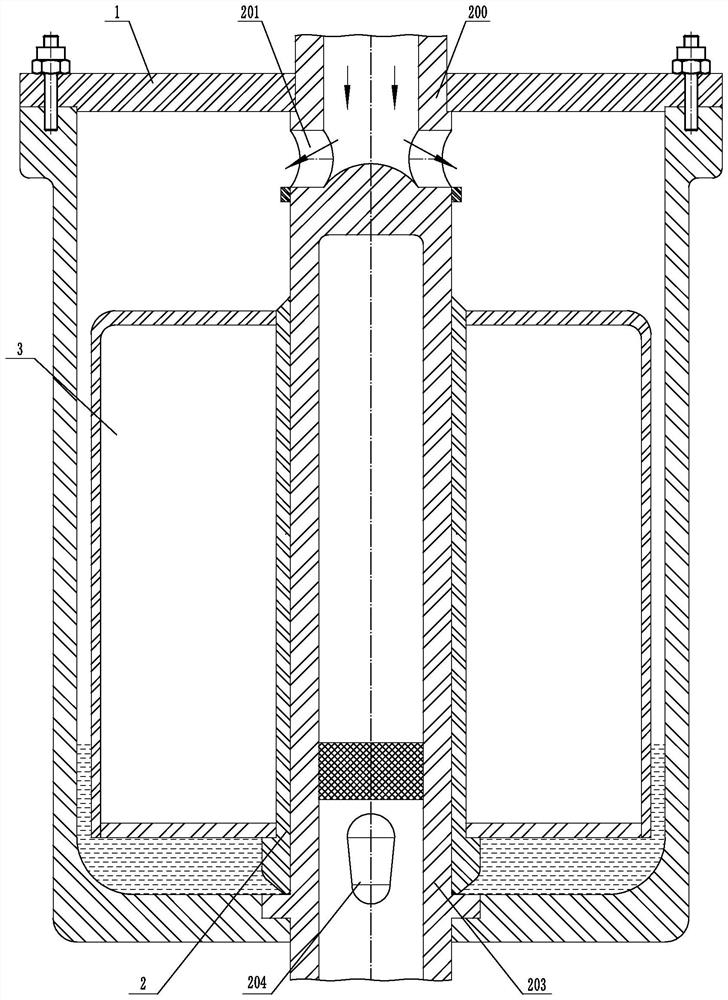
[0050] attached figure 1 As shown, at this time, the condensed water in the inner cavity of the valve body 1 is at the lowest position, the valve core sleeve 2 is closely attached to the dead discharge pipe 203 with the valve seat, and at the same time, the condensed water seals off the sealing pair.

[0051] second embodiment

no. 2 example

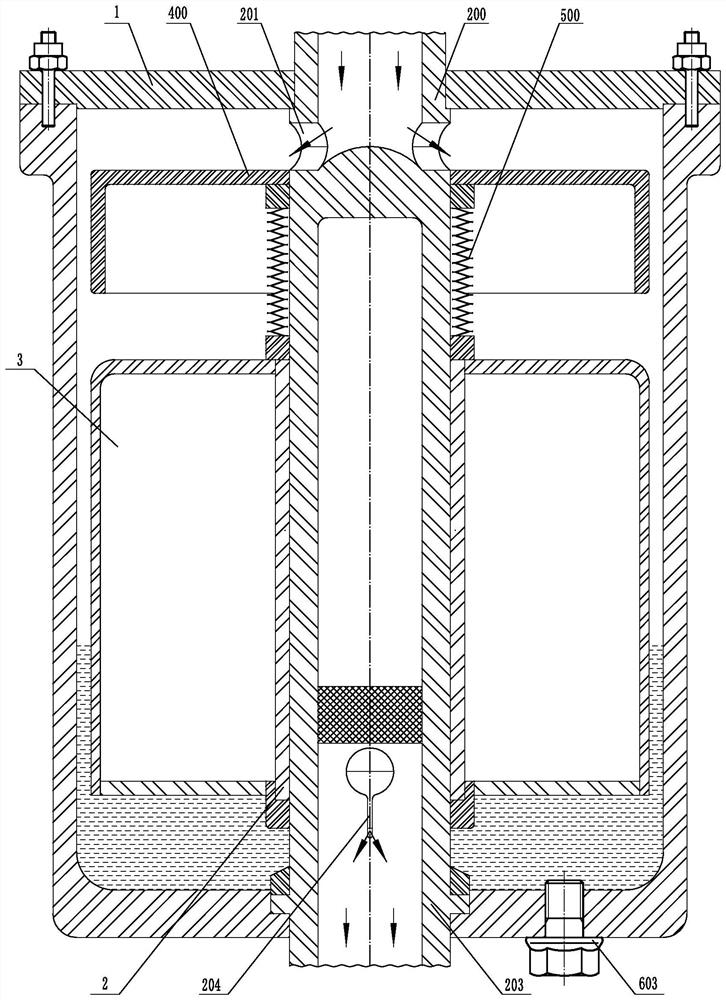
[0053] attached figure 2 As shown, at this time, the condensed water in the inner cavity of the valve body 1 is at a middle-low level, the lower end of the valve core sleeve 2 leaves the valve seat, a small amount of condensed water is discharged, and the pressure in the inner cavity of the valve body 1 presses the sealing cover plate 6 .

[0054] third embodiment

no. 3 example

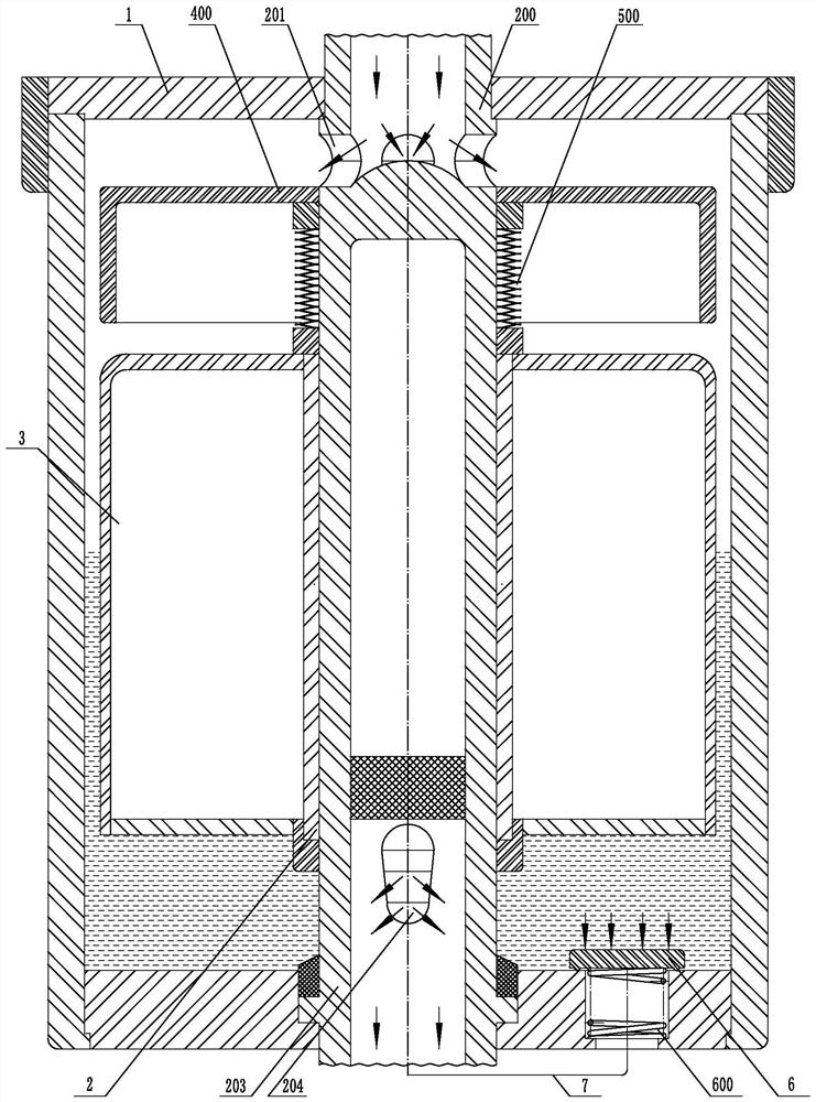
[0056] attached image 3 As shown, at this time, the condensed water in the inner cavity of the valve body 1 is at a high level, and a large amount of condensed water is discharged. At the same time, the pressure in the inner cavity of the valve body 1 presses the sealing cover plate 6 .

[0057] attached Figure 4 As shown, at this time, the pipe network is in three states: 1. The pipe network has just stopped working, and the inner cavity of the pipe network loses pressure. There is a vacuum in the pipe network; 2. The pipe network is in a non-working state; 3. The pipe network has just started to work, and the compression spring A600 still lifts the sealing cover 6, and a small amount of pressure appears in the inner cavity of the pipe network, blowing off the air in the inner cavity of the pipe network , exhaust gas and residual condensate.

[0058] Fourth embodiment


PUM


Abstract

According to the whole-course flow self-regulation uninterrupted discharge drain valve, the upper part of a valve element pipe is divided into an air inlet blind pipe or an air inlet pipe, the lower part of the valve element pipe is divided into a discharge blind pipe or a discharge blind pipe with a valve seat, the upper part and the lower part of the valve element pipe are integrated or axially separated, and the air inlet blind pipe or the air inlet pipe vertically penetrates through and is connected with a top plate of a valve body; the discharge blind pipe with the valve seat penetrates through and is connected with a bottom plate of the valve body or the discharge blind pipe is attached to and separated from the bottom plate of the valve body, in an inner cavity of the valve body, the air inlet blind pipe or the air inlet pipe is provided with at least one radial air inlet hole, and the discharge blind pipe with the valve seat or the discharge blind pipe with the valve seat is provided with at least two radial discharge holes which are uniformly distributed; the valve core sleeve coaxial with the floating ball wraps the valve core pipe and slides up and down in the axial direction, the discharge hole is opened and covered, condensate water is discharged and cut off, and the valve core sleeve and the discharge blind pipe with the valve seat form a sealing pair; the device has the advantages of erosion prevention, zero leakage, large discharge capacity, vacuum breaking, waste gas removal, dreg discharge, safety, reliability and energy conservation.

Description

technical field [0001] The whole flow self-adjusting uninterrupted discharge trap belongs to the field of valves and is an original invention in the field of traps. It involves the drainage of various working conditions, including the drainage of vacuum pipe networks, the drainage of toxic and harmful medium pipe networks, and the drainage of flammable and explosive media pipes. The water drainage of the network, the water drainage of the nuclear energy medium pipe network, and the water drainage of the steam pipe network; its energy-saving effect is in line with the country's strategic goals. [0002] The present invention has following characteristics: [0003] 1. When the condensed water in the inner cavity of the valve drops or rises greatly, the floating ball drives the valve core sleeve to move up and down in the axial direction to cover and open the discharge hole, cut off and discharge the condensed water, and the floating ball and the valve core sleeve are not affecte...

Claims


Application Information

Patent Timeline
Patent Type & Authority Applications(China)
IPC IPC(8): F16T1/18F16T1/38
CPCF16T1/18F16T1/38
Inventor 卢星霖
Owner 卢星霖
Learn More