Garbage pyrolysis gasification furnace capable of catalyzing circulation of pyrolysis flue gas and working method of garbage pyrolysis gasification furnace

A technology of pyrolysis gasification and flue gas circulation, which is applied in gasification process, granular/powder fuel gasification, petroleum industry, etc., and can solve the problems of reducing the calorific value of syngas, high tar treatment cost, uneven heating, etc. , to achieve the effect of maintaining the heating temperature

Pending Publication Date: 2020-11-24
UNIV OF SCI & TECH LIAONING
View PDF0 Cites 0 Cited by
  • Summary
  • Abstract
  • Description
  • Claims
  • Application Information

AI Technical Summary

Problems solved by technology

However, also because the pyrolysis process is carried out in an oxygen-deficient atmosphere and high temperature conditions, there will be a large amount of pyrolysis tar in the pyrolysis synthesis gas, which has become one of the problems hindering the large-scale application of solid waste pyrolysis technology
Pyrolysis tar will not only affect the gas quality of syngas, reduce the calorific value of syngas, but also condense in downstream equipment and affect its normal operation
At present, the application of pyrolysis technology in waste treatment still has problems such as high cost of tar treatment, low calorific value of synthesis gas, and uneven heating in the pyrolysis process.

Method used


Image

  • Garbage pyrolysis gasification furnace capable of catalyzing circulation of pyrolysis flue gas and working method of garbage pyrolysis gasification furnace
  • Garbage pyrolysis gasification furnace capable of catalyzing circulation of pyrolysis flue gas and working method of garbage pyrolysis gasification furnace
  • Garbage pyrolysis gasification furnace capable of catalyzing circulation of pyrolysis flue gas and working method of garbage pyrolysis gasification furnace

Examples


Embodiment Construction

[0038] The specific embodiment of the present invention will be further described below in conjunction with accompanying drawing:

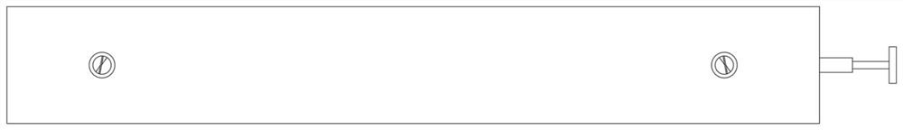
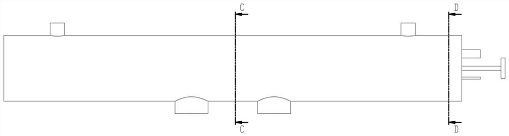
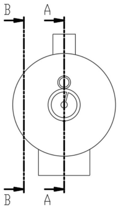
[0039] Such as Figure 1-Figure 7 As shown, a waste pyrolysis gasification furnace for catalytic pyrolysis flue gas circulation according to the present invention includes a pyrolysis gasification furnace body 1, a material conveying screw 1 and a combustion chamber casing 3; the pyrolysis gasification furnace Body 1 is composed of furnace body, pyrolysis material feed port 4, catalyst feed port 6, porous carbon collection port 5, catalyst collection port 7, circulating flue gas inlet 15, synthesis gas outlet pipe 8 and synthesis gas branch pipe 9; The furnace body is arranged horizontally, the top of one end of the furnace body is provided with a pyrolysis material feed port 4, and the top of the other end of the furnace body is provided with a catalyst feed port 6; the bottom of the furnace body near the center of the furnace body is provided wi...


PUM


Abstract

The present invention relates to a garbage pyrolysis gasification furnace capable of catalyzing circulation of pyrolysis flue gas and a working method of the garbage pyrolysis gasification furnace. The garbage pyrolysis gasification furnace comprises a pyrolysis gasification furnace body, a material conveying screw and a combustion chamber sleeve pipe; the pyrolysis gasification furnace body is composed of a furnace body, a pyrolysis material inlet, a catalyst inlet, a porous carbon collecting port, a catalyst collecting port, a circulating flue gas inlet, a synthesis gas outlet pipe and a synthesis gas branch; an inside space of the furnace body is divided into a pyrolysis area and a gasification area according to functions; and an outer end of the furnace body corresponding to one end ofthe synthesis gas outlet pipe and the combustion chamber sleeve pipe are separated into a combustion area by gas baffle plates, and the remaining part between the combustion chamber sleeve pipe and the furnace body forms a jacketed heat exchange structure. The garbage pyrolysis gasification furnace can realize continuous feeding, and is also more even in heating during the pyrolysis process, higher in quality of synthesis gas and lower in content of harmful pollutants and tar.

Description

technical field [0001] The invention relates to the technical field of garbage treatment, in particular to a garbage pyrolysis gasifier for catalytic pyrolysis flue gas circulation and a working method thereof. Background technique [0002] Pyrolysis technology is an emerging technology to solve the disadvantages of municipal waste incineration technology and realize the efficient and harmless treatment of solid waste. Since the heating process of waste pyrolysis technology is carried out in an oxygen-deficient atmosphere, less toxic pollutants containing oxygen are produced, and the generated syngas has a higher calorific value, a smaller volume, and a higher added value of by-products Porous carbon materials are beneficial to meet different energy demands. However, also because the pyrolysis process is carried out in an oxygen-deficient atmosphere and high temperature conditions, there will be a large amount of pyrolysis tar in the pyrolysis synthesis gas, which has becom...

Claims


Application Information

Patent Timeline
Patent Type & Authority Applications(China)
IPC IPC(8): C10J3/48C10J3/50
CPCC10J3/48C10J3/50C10J2300/0946C10J2300/0959
Inventor 李先春林建廷王晴王焕然
Owner UNIV OF SCI & TECH LIAONING
Why Eureka
Try Eureka