Supercharge Your Innovation With Domain-Expert AI Agents!

Touch panel, method for determining touch points, and display device

A technology for touch panels and determination methods, applied in the input/output process of data processing, instruments, electrical digital data processing, etc., can solve the problems of large resistance, inaccuracy, and inaccurate position, etc., and reduce the resistance of resistance value, the effect of accurate positioning

Active Publication Date: 2017-02-15
BOE TECH GRP CO LTD
View PDF4 Cites 0 Cited by
  • Summary
  • Abstract
  • Description
  • Claims
  • Application Information

AI Technical Summary

Problems solved by technology

[0006] The inventor finds that there are at least the following problems in the prior art: From the equivalent circuit diagram ( figure 2 ) can be obtained, calculate the Y coordinate, X+ is used as the lead-out to measure the voltage Ux of the contact point, and when calculating the X-coordinate, Y+ is used as the lead-out to measure the voltage Uy of the contact point, Due to the large resistance value of the resistor, the measured voltage Ux and Uy of the contact point will be inaccurate, resulting in the inaccurate calculated position of the touch point and the problem of low sensitivity of the touch panel

Method used


Image

  • Touch panel, method for determining touch points, and display device
  • Touch panel, method for determining touch points, and display device
  • Touch panel, method for determining touch points, and display device

Examples


Embodiment 1

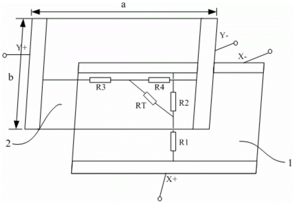
[0064] like Figure 4 As shown, the present embodiment provides a touch panel, the first transparent conductive layer 1 and the second transparent conductive layer 2 are arranged at intervals opposite to each other, and the first transparent conductive layer 1 is provided with a first voltage signal terminal X+ and a A second voltage signal terminal X- opposite to a voltage signal terminal X+, a third voltage signal terminal Y+ and a fourth voltage signal terminal Y- opposite to the third voltage signal terminal Y+ are arranged on the second transparent conductive layer 2, wherein , the extension direction of the first voltage signal terminal X+ is perpendicular to the extension direction of the third voltage signal terminal Y+, the second signal voltage terminal and the fourth voltage signal terminal Y- are shorted together, and the touch panel further includes : a voltage output unit, a reading unit, and a calculation unit; the voltage output unit is used to alternately inpu...

Embodiment 2

[0081] The present embodiment provides a method for determining a touch point of a touch panel, wherein the touch panel is the above-mentioned touch panel, and the method specifically includes:

[0082] The driving voltage is alternately input to the first voltage signal terminal X+ and the third voltage signal terminal Y+, and the low voltage is input to the second voltage signal terminal X- and the fourth voltage signal terminal Y- shorted together at the same time.

[0083] When the driving voltage is input to the first voltage signal terminal X+, the voltage value of the third voltage signal terminal Y+ is read; when the driving voltage is input to the third voltage signal terminal Y+, the voltage value of the first voltage signal terminal X+ is read.

[0084] The coordinates of the touch point are calculated according to the read voltage value of the third voltage signal terminal Y+ and the read voltage value of the first voltage signal terminal X+.

[0085] Preferably, t...

Embodiment 3

[0105] This embodiment provides a display device, which includes the touch panel in the first embodiment, so the sensitivity of the display device of this embodiment is relatively high.

[0106] The display device can be any product or component with a display function, such as a mobile phone, a tablet computer, a TV, a monitor, a notebook computer, a digital photo frame, a navigator, and the like.

[0107] Of course, the display device of this embodiment may also include other conventional structures, such as a display driving unit and the like.


PUM


Abstract

The invention provides a touch panel, a method for determining a touch point, and a display device, which belong to the technical field of display devices and can solve the problem of low sensitivity of the existing touch panel. The touch panel of the present invention includes: a first transparent conductive layer and a second transparent conductive layer arranged at intervals, and a first voltage signal terminal and a second voltage signal terminal opposite to the first voltage signal terminal are arranged on the first transparent conductive layer The signal terminal is provided with a third voltage signal terminal and a fourth voltage signal terminal opposite to the third voltage signal terminal on the second transparent conductive layer, wherein the extending direction of the first voltage signal terminal is perpendicular to the extending direction of the third voltage signal terminal , the second signal voltage terminal and the fourth voltage signal terminal are short-circuited together, and the touch panel further includes: a voltage output unit, a reading unit, and a calculation unit.

Description

technical field [0001] The invention belongs to the field of display technology, and in particular relates to a touch panel, a method for determining a touch point, and a display device. Background technique [0002] At present, the structure of the four-wire resistive touch screen is as follows: figure 1 As shown, the substrate is covered with two transparent conductive ITO layers (namely, the first transparent conductive layer 1 and the second transparent conductive layer 2), which are respectively used as X electrodes and Y electrodes, and the two layers are insulated from each other. Among them, the ITO of the lower layer is attached to the glass substrate, and the ITO of the upper layer is attached to the PET film. The positive and negative ends of the X electrode and the Y electrode are respectively drawn from the two ends by the "conductive strip" (the black strip part in the figure), and the positions of the X electrode and the Y electrode conductive strip are perpe...

Claims


Application Information

Patent Timeline
Patent Type & Authority Patents(China)
IPC IPC(8): G06F3/045
CPCG06F3/045G06F2203/04113G06F3/0416G06F3/0412G06F2203/04112
Inventor 刘晓龙
Owner BOE TECH GRP CO LTD
Features
  • R&D
  • Intellectual Property
  • Life Sciences
  • Materials
  • Tech Scout
  • Unparalleled Data Quality
  • Higher Quality Content
  • 60% Fewer Hallucinations
Learn More