A flat display panel

A flat-panel display, panel technology, applied in static indicators, instruments, etc., to reduce the effect of the difference

Active Publication Date: 2017-01-18
CHINA STAR OPTOELECTRONICS INT HK
View PDF7 Cites 0 Cited by
  • Summary
  • Abstract
  • Description
  • Claims
  • Application Information

AI Technical Summary

Problems solved by technology

However, since the pixel circuits P5, P4, and P1 are respectively affected by different degrees of feedthrough effects, even if you want to compensate the stored data potential, you cannot simply achieve the goal

Method used


Image

  • A flat display panel
  • A flat display panel
  • A flat display panel

Examples


Embodiment Construction

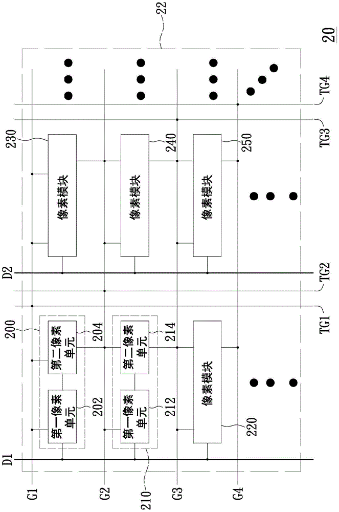
[0037] Please refer to figure 2 , which is a circuit block diagram of a flat panel display according to an embodiment of the present invention. In this embodiment, the flat panel display 20 includes data lines D1 , D2 , gate lines G1 , G2 , G3 , G4 , gate guide lines TG1 , TG2 , TG3 , TG4 and a display area 22 . As shown in the figure, the gate lines G1 - G4 extend along the direction of the coordinate axis X, while the data lines D1 and D2 and the gate guiding lines TG1 - TG4 extend along the direction of the coordinate axis Y. Furthermore, each of the gate guiding lines TG1, TG2, TG3 and TG4 is electrically coupled to a corresponding gate line G1, G2, G3 and G4, so that the gate guiding lines TG1, TG2, TG3 and TG4 can be The potentials of the signals transmitted in the corresponding gate lines G1, G2, G3 and G4 are respectively controlled. In addition, in order to control the displayed results conveniently, in this embodiment, the gate lines G1-G4, the data lines D1, D2, ...


PUM


Abstract

A flat display panel includes a plurality of gate lines, a plurality of data lines, a plurality of tracking gate lines and a display area. The display area is disposed with pixel modules therein. Each pixel module includes a first pixel unit and a second pixel unit. The first pixel unit is configured to determine whether to receive a data transmitted on the first predetermined data line according to a voltage level of the first predetermined gate line. The second pixel unit is configured to determine whether to receive a voltage level of the second predetermined gate line according to a voltage level of the first predetermined gate line and determine whether to receive a data from the first pixel unit according to a voltage level received from the second predetermined gate line.

Description

technical field [0001] The present invention relates to a flat display panel, in particular to a flat display panel suitable for narrow frame design. Background technique [0002] With the rapid development of flat-panel display technology, technologies for reducing the width of the frame of the flat-panel display in order to increase the viewing area are constantly being introduced. Please refer to figure 1 , which is a circuit diagram of a Tracking Gate Line in Pixel used in the background technology. The circuit of this technology does not need to provide fan-out (Fan out) connection circuits on both sides of the panel at all, and does not need to set shift registers on both sides of the panel, so the border width on both sides of the panel can be minimized. [0003] However, if figure 1 As shown, in order to control the pixel circuits P1, P2 and P3, the potentials of the gate lines G1, G2 and G3 must be controlled respectively. For this, the gate guiding line TG1 is ...

Claims


Application Information

Patent Timeline
Patent Type & Authority Patents(China)
IPC IPC(8): G09G3/20
CPCG09G3/20G09G3/3607G09G3/3648G09G3/3659G09G2320/0219
Inventor 廖伟见
Owner CHINA STAR OPTOELECTRONICS INT HK
Why Eureka
Try Eureka