Unlock instant, AI-driven research and patent intelligence for your innovation.

Intelligent Power Module

A technology of intelligent power modules and power devices, applied in the field of electronics, can solve problems such as power grid interference, affecting the service life of intelligent power modules, and large heat generation

Active Publication Date: 2018-02-16
GUANGDONG MIDEA GRP WUHU REFRIGERATING EQUIP CO LTD
View PDF5 Cites 0 Cited by
  • Summary
  • Abstract
  • Description
  • Claims
  • Application Information

AI Technical Summary

Problems solved by technology

In order to ensure that the intelligent power module can work normally when the duty cycle of the driving signal is large or small, in the prior art, the switching speed of the power device (IGBT tube) inside the intelligent power module is usually designed very fast, so that The rise time and fall time of the signal of the U-phase high-voltage area power supply negative terminal, the V-phase high-voltage area power supply negative terminal, and the W-phase high-voltage area power supply negative terminal of the intelligent power module are very fast, resulting in a large ringing, causing The switching loss of the intelligent power module is very large, which causes the heat generated by the intelligent power module to be very large, which affects the service life of the intelligent power module. At the same time, because the switching speed of the intelligent power module is too fast, it causes its interference is also very serious
[0003] In the prior art, in order to reduce the temperature of the intelligent power module, a huge radiator has to be installed on the back of the intelligent power module, and the power device inside the intelligent power In the industry, the development of frequency conversion electric control boards that match smart power modules requires a lot of time and manpower to design shielding smart power modules from interfering with the power grid, which undoubtedly greatly increases the development cost of smart power modules, thereby hindering smart Large-scale promotion of power modules in the field of inverter air conditioners

Method used


Image

  • Intelligent Power Module
  • Intelligent Power Module
  • Intelligent Power Module

Examples


Embodiment Construction

[0046] It should be understood that the specific embodiments described here are only used to explain the present invention, not to limit the present invention.

[0047] The invention provides a communication power storage battery anti-reverse connection circuit.

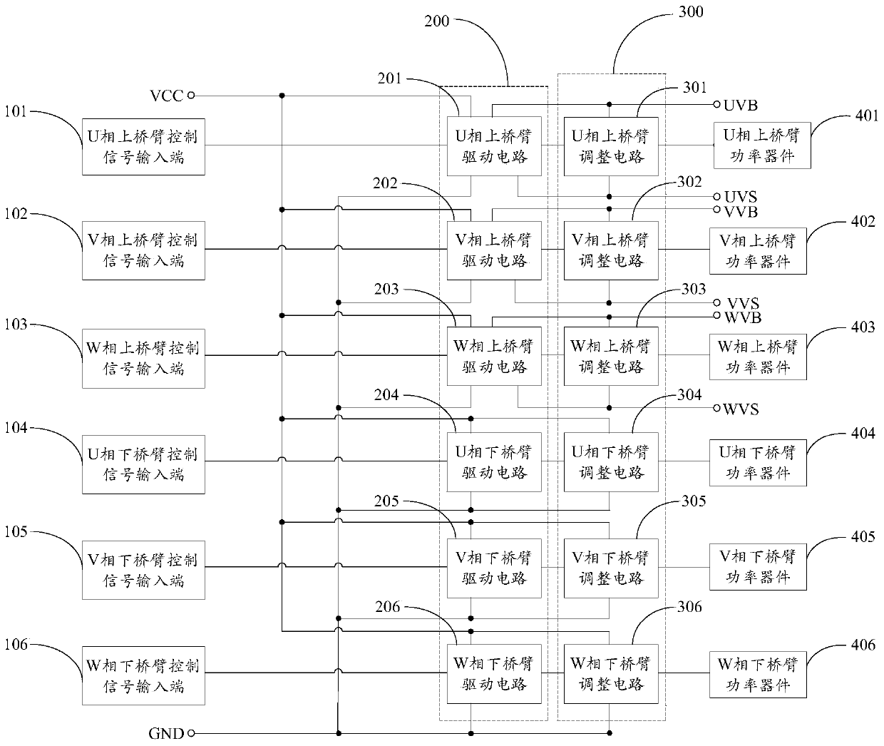
[0048] refer to figure 1 , figure 1 It is a schematic diagram of the module structure of an embodiment of the intelligent power module of the present invention.

[0049]In this embodiment, the intelligent power module includes a U-phase upper bridge arm control signal input end 101, a V-phase upper bridge arm control signal input end 102, a W-phase upper bridge arm control signal input end 103, and a U-phase lower bridge arm control signal input end. Input terminal 104, V-phase lower bridge arm control signal input terminal 105, W-phase lower bridge arm control signal input terminal 106, low-voltage zone power supply positive terminal VCC, low-voltage zone power supply negative terminal GND, U-phase high-voltage zo...


PUM


Abstract

The invention discloses an intelligent power module which comprises a U-phase upper bridge arm power device, a V-phase upper bridge arm power device, a W-phase upper bridge arm power device, a U-phase lower bridge arm power device, a V-phase lower bridge arm power device, a W-phase lower bridge arm power device, a drive circuit unit and an adjustment circuit unit. The drive circuit unit is used for driving the switching actions of the U-phase upper bridge arm power device, the V-phase upper bridge arm power device, the W-phase upper bridge arm power device, the U-phase lower bridge arm power device, the V-phase lower bridge arm power device and the W-phase lower bridge arm power device. The adjustment circuit unit is used for adjusting the switching speeds of the U-phase upper bridge arm power device, the V-phase upper bridge arm power device, the W-phase upper bridge arm power device, the U-phase lower bridge arm power device, the V-phase lower bridge arm power device and the W-phase lower bridge arm power device. By means of the intelligent power module, the switching loss is reduced, and disturbance to the power grid is reduced.

Description

technical field [0001] The invention relates to the field of electronic technology, in particular to an intelligent power module. Background technique [0002] In the actual application of the intelligent power module, especially when it is applied to the inverter air conditioner, the power device (IGBT tube) inside the intelligent power module is driven by a driving signal of a certain frequency according to different application occasions, and the duty of the driving signal is The duty ratio of the driving signal also varies, and at the same time, the duty ratio of the driving signal may be large (eg, about 50%) or small. In order to ensure that the intelligent power module can work normally when the duty cycle of the driving signal is large or small, in the prior art, the switching speed of the power device (IGBT tube) inside the intelligent power module is usually designed very fast, so that The rise time and fall time of the signal of the U-phase high-voltage area powe...

Claims


Application Information

Patent Timeline
Patent Type & Authority Patents(China)
IPC IPC(8): H02M7/00H02M1/44
CPCH02M1/088
Inventor 冯宇翔
Owner GUANGDONG MIDEA GRP WUHU REFRIGERATING EQUIP CO LTD