
A method for power calibration of transmitting/receiving equipment

A technology for power calibration and receiving equipment, which is applied in transmitter monitoring, receiver monitoring, etc., can solve problems such as insufficient accuracy, and achieve the effect of improving power accuracy and high calibration accuracy

Active Publication Date: 2016-08-24
深圳市极致汇仪科技有限公司
View PDF3 Cites 0 Cited by
  • Summary
  • Abstract
  • Description
  • Claims
  • Application Information

AI Technical Summary

Problems solved by technology

[0007] In order to solve the technical problem of insufficient precision of the power calibration of the existing receiving / transmitting channel under broadband signals, the present invention proposes a method for calibrating the power of transmitting / receiving equipment, which includes the following steps:

Method used


Image

  • A method for power calibration of transmitting/receiving equipment
  • A method for power calibration of transmitting/receiving equipment
  • A method for power calibration of transmitting/receiving equipment

Examples


Embodiment Construction

[0025] The present invention will be further described below in conjunction with the accompanying drawings and specific embodiments.

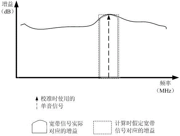
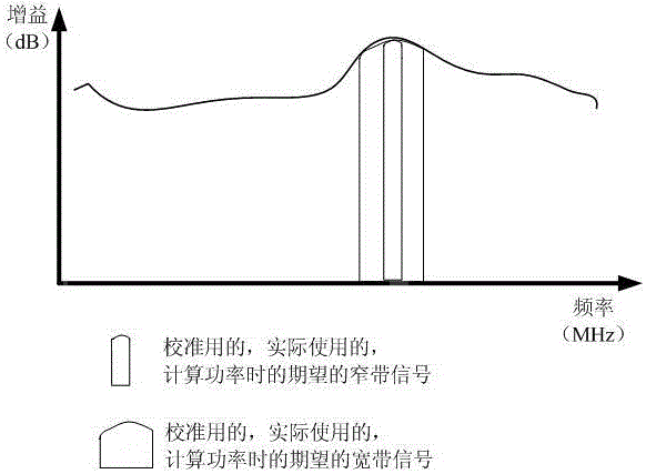
[0026] In order to solve the technical problems raised in the background technology of this case, the channel gain curve adopts the same bandwidth as the actual signal to be sent, such as figure 2 The way to obtain the curve during calibration is to transmit a signal with known source power at different frequency points within the frequency band corresponding to the rectangle, and then measure the output power of the transmitter. The gain value of the frequency point within the bandwidth can be obtained by subtracting the source power from the received power. For different bandwidths, use the same method to obtain the corresponding gain curves (ie, calibration values). In this way, different frequency points of the same bandwidth have different calibration values.

[0027] However, this method needs to calibrate all the different frequency po...


PUM


Abstract

The invention provides a power calibration method of transmitting / receiving equipment. The method comprises the first step that N frequency points are sampled on a frequency spectrum at even intervals, and a gain calibration value GSt corresponding to a single frequency signal fSt generated by power PIN is obtained; the second step that a gain calibration value GB11 corresponding to a wideband signal B11 generated by the power PIN is obtained, wherein the bandwidth of the wideband signal B11 is W1, the lower limiting frequency of the wideband signal B11 is f11L and the upper limiting frequency of the wideband signal B11 is f11H; the third step that a gain calibration value GB 12 corresponding to a wideband signal B12 generated by the power PIN is calculated as follows: if J-M<K<J, the following formula is satisfied (see instructions,) and if J<M<J+M, the following formula is satisfied (see instructions), wherein the bandwidth of the wideband signal B12 is W1, the lower limiting frequency of the wideband signal B12 is f12L and the upper limiting frequency of the bandwidth signal B12 is f12H.

Description

technical field [0001] The invention relates to a method for calibrating the power of a transmitting device or a receiving device. Background technique [0002] Both the transmitter and the receiver need to be able to transmit a signal of a specified power more accurately, or to receive a signal of a specified power more accurately, especially for test instruments, the power accuracy is even a direct evaluation of whether a set of instruments is qualified most important indicator. [0003] The so-called power accuracy is: for the transmitter, the transmitter is required to send (that is, the front end of the transmitter) a certain power, and the actual power at the transmitter port (and the back end of the transmitter) is different from the specified power. The smaller the difference is, the more accurate it is; for the receiver, a signal with a certain power is poured into the receiver port (ie, the front end of the transmitter), and the signal measured by the receiver (ie...

Claims


Application Information

Patent Timeline
Patent Type & Authority Patents(China)
IPC IPC(8): H04B17/13H04B17/21
Inventor 别体军朱涛李伟东
Owner 深圳市极致汇仪科技有限公司
Learn More