Method and system for network topology

A technology of network topology and network topology diagram, which is applied in the field of communication, can solve problems such as difficult implementation, achieve the effect of enriching functions and speeding up the convergence speed

Active Publication Date: 2015-01-21
NANJING ZHONGXING SOFTWARE
View PDF6 Cites 7 Cited by
  • Summary
  • Abstract
  • Description
  • Claims
  • Application Information

AI Technical Summary

Problems solved by technology

Because resource information is isolated between control domains, the resource information flooded between domains is only abstract content, and some functions in the business of a single control domain are difficult to implement in cross-domain services

Method used


Image

  • Method and system for network topology
  • Method and system for network topology
  • Method and system for network topology

Examples


Embodiment 1

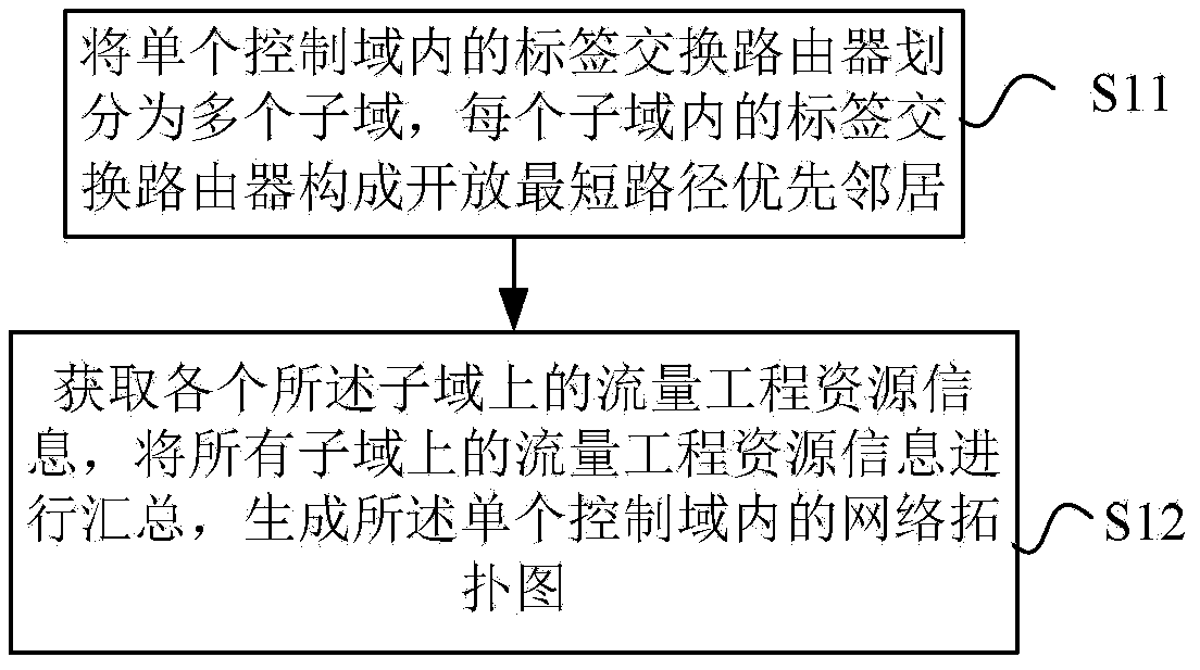
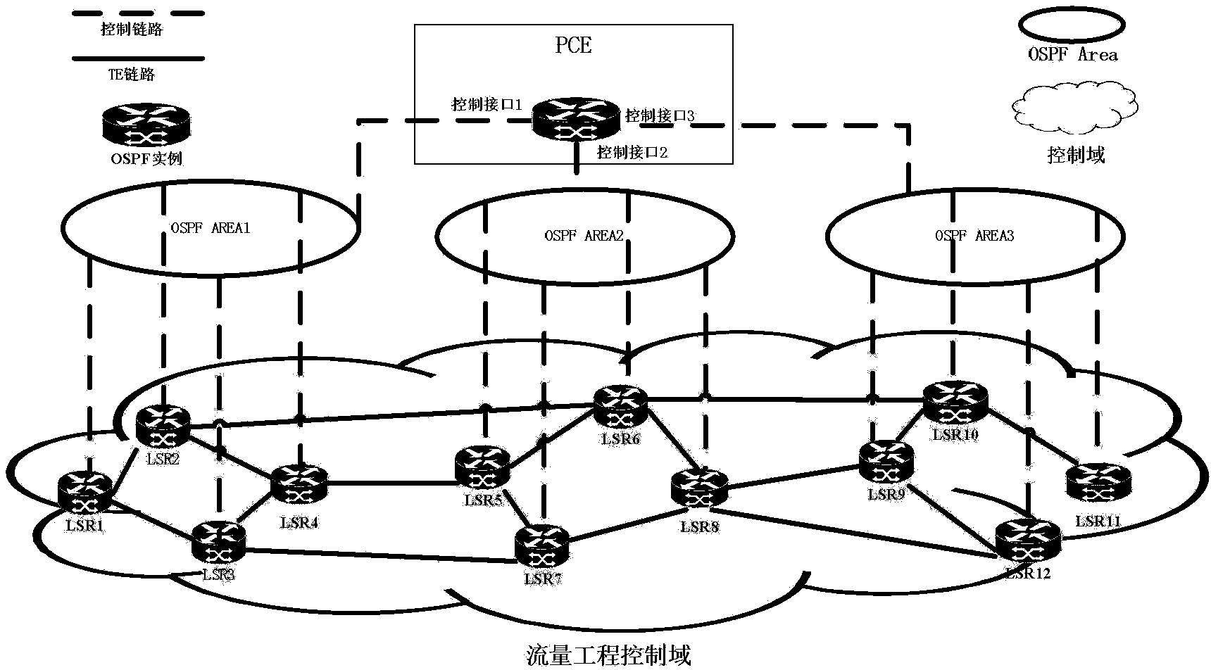
[0045] Combine below figure 2 Illustrate the embodiment of the present invention, the traffic engineering resource information on all LSRs has been configured in advance, including steps:

[0046] Step 101: Divide the LSRs in the control domain into different OSPF Areas, assign a separate OSPF Area id greater than 0 to each area, and configure the OSPF Area id on the control interface of the LSR.

[0047] According to the flooding regulations of OSPF-TE, LSRs in the same OSPF Area can form neighbors. The traffic engineering resource information on LSRs is flooded through Opaque LSAs of type 10, and will only be flooded to the control interfaces of other LSRs that form neighbors. , that is, it will only be flooded in each sub-area, but will not be flooded to other OSPF Areas.

[0048] Such as figure 2 As shown in the figure, the control interfaces of LSR1, LSR2, LSR3, and LSR4 are configured with OSPF Area1, the control interfaces of LSR5, LSR6, LSR7, and LSR8 are configure...

Embodiment 2

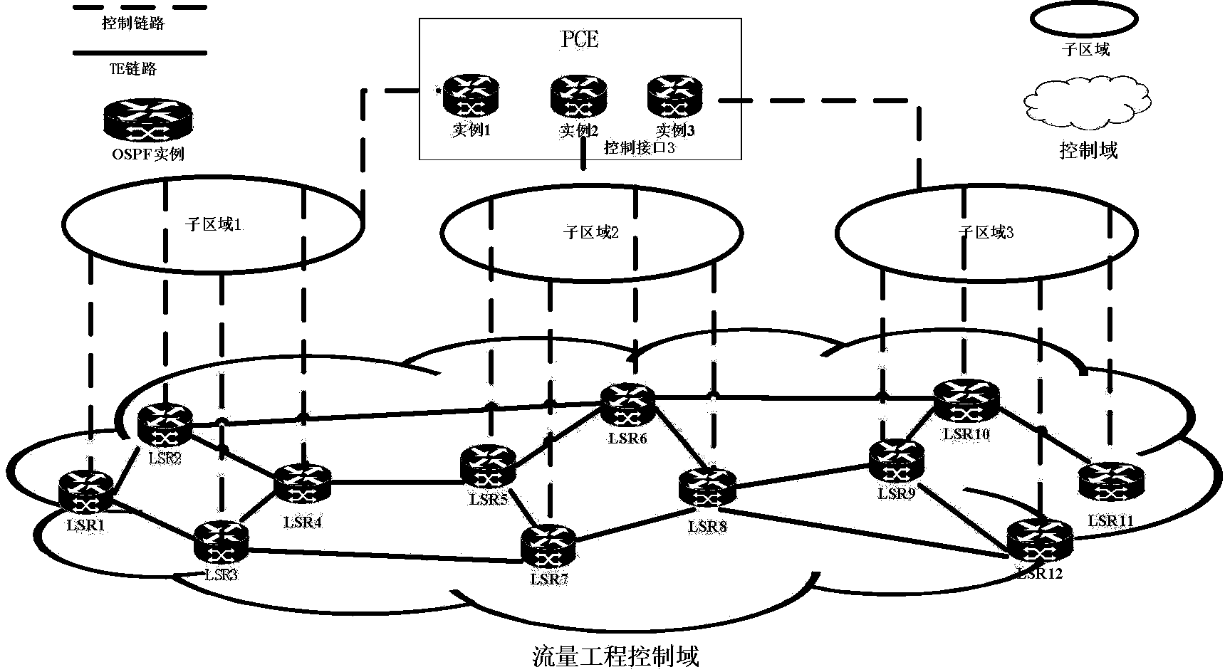
[0057] Combine below image 3 Embodiments of the present invention will be described. The traffic engineering resource information on all LSRs has been configured in advance, start the following steps:

[0058] Step 201, divide the LSRs in the control domain into different sub-areas, the LSRs in each sub-area form OSPF neighbors, and the LSRs in different sub-areas cannot form OSPF neighbors.

[0059] Such as image 3 As shown, the control interfaces of LSR1, LSR2, LSR3, and LSR4 belong to subarea 1, the control interfaces of LSR5, LSR6, LSR7, and LSR8 belong to subarea 2, and the control interfaces of LSR9, LSR10, LSR11, and LSR12 belong to subarea 3. According to the DCN network status, neighbors can be formed. LSRs in each sub-area can be configured as neighbors, but LSRs between sub-areas cannot be configured as neighbors.

[0060] Step 202, introduce PCE in the entire control domain, start an OSPF protocol processing instance on the PCE for each sub-area divided, and c...


PUM


Abstract

A method and system for network topology. The method includes: dividing Label Switching Routers in a single control area into multiple sub-areas, wherein the Label Switching Routers in each sub-area constitute Open Shortest Path First neighbors; obtaining Traffic Engineer resource information on each said sub-area, collecting the Traffic?Engineer resource information on all the sub-areas, and generating a network topology diagram in the single control area.

Description

technical field [0001] The invention relates to the field of communication technology, in particular to a network topology method and system. Background technique [0002] MPLS-TE (Multi-Protocol Label Switching-Traffic Engineer, multi-protocol label switching traffic engineering) combines the advantages of multi-protocol label switching technology and traffic engineering technology, and realizes the dynamics of network bandwidth resources in packet switching and layer 2 switching Adjust and optimize the configuration. GMPLS (Generalized Multi-Protocol Label Switching) is a further extension of MPLS-TE. It can not only support IP (Internet Protocol, network protocol) packet switching, but also support time slot switching, Wavelength switching and space switching (such as fiber switching and port switching). [0003] The resource information of traffic engineering is flooded to all Label Switching Routers (LSRs) in the control domain through routing protocols. Each LSR can f...

Claims


Application Information

Patent Timeline
Patent Type & Authority Applications(China)
IPC IPC(8): H04L12/721H04L12/723H04L12/751H04L45/02H04L45/50
CPCH04L12/6418H04L45/02H04L41/0853H04L41/12H04L45/50H04L45/12
Inventor 罗春王志宏
Owner NANJING ZHONGXING SOFTWARE
Why Eureka
Try Eureka