
Electric spindle for numerical control machines

一种数控机床、电主轴的技术,应用在铣床、铣床设备、金属加工机械零件等方向,能够解决电主轴重量降低等问题

Active Publication Date: 2015-01-21
FCS SYST
View PDF6 Cites 4 Cited by
  • Summary
  • Abstract
  • Description
  • Claims
  • Application Information

AI Technical Summary

Problems solved by technology

[0014] Even the detachable tool holder spindle has an overall weight of several tens of kilograms despite the significant weight reduction relative to the overall electrospindle, with all the drawbacks that accompany such a situation during spindle replacement

Method used


Image

  • Electric spindle for numerical control machines
  • Electric spindle for numerical control machines
  • Electric spindle for numerical control machines

Examples


Embodiment Construction

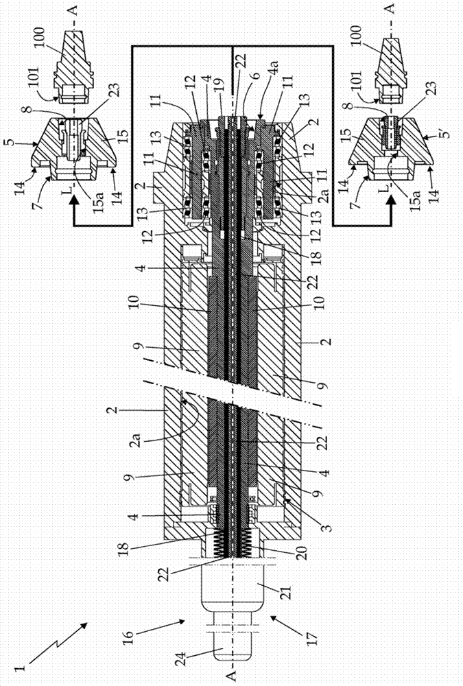
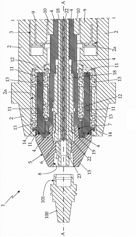
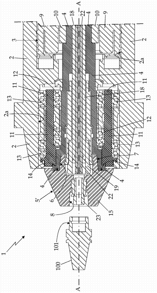
[0022] refer to figure 1 , figure 2 with image 3 , reference numeral 1 denotes an integral motorized spindle for numerically controlled machine tools, which has a longitudinal reference axis A and is configured to selectively lock the universal tool 100 and drive the universal The tool 100 rotates. The electro-spindle 1 has also been found to be particularly advantageous for use in numerically controlled grinding machines.

[0023] The electro-spindle 1 basically comprises: an outer structural housing 2 configured to be rigidly attachable to the spindle bracket or slide (not shown) of any CNC grinding or similar machine tool; an electric motor 3 , the electric motor 3 is stably housed in the structural housing 2 and is provided with a drive shaft 4 which protrudes / exposes with its front end 4a to the structural housing while remaining partially coaxial with the electric spindle axis A the exterior of the body 2; and at least one tool holder head 5 configured to be attach...


PUM


Abstract

Electric spindle (1) for numerical control machines structured to lock and rotationally drive a tool (100) about a predetermined reference axis (A) locally coinciding with the longitudinal axis of the tool (2); the electric spindle (1) comprising: an outer structural casing (2) that is structured to be rigidly attachable to a generic numerical control machine; an electric motor (3) that is housed within the structural casing (2) and is provided with a drive shaft (4), which projects / emerges with its front end (4a) outside the structural casing (2) while remaining locally coaxial to the reference axis (A) of the electric spindle; a rotating thrust- bearing bushing or sleeve (11), which is fitted in an axially rotatable manner on the front end (4a) of the drive shaft (4) via interposition of a first set of annular rolling bearings (12), and is maintained coaxial to the reference axis (A) of the electric spindle by a second set of annular rolling bearings (13), which are interposed between the rotating bushing or sleeve (11) and the structural casing (2); and at least one disassemblable tool-holder head (5, 5') that is structured to be attachable, in a rigid and stable though easily releasable manner, to the front end (4a) of the drive shaft (4), is structured so as to accommodate and retain, in a rigid and stable though easily releasable manner, the shank (101) of a generic tool (100) for numerical control machines, and is provided with a peripheral crown (14) that is dimensioned / structured to stably abut, selectively and alternatively, on the front end (4a) of the drive shaft (4) or on the rotating thrust-bearing bushing or sleeve (11).

Description

technical field [0001] The invention relates to an electric spindle for a numerically controlled machine tool. [0002] More specifically, the invention relates to an electric spindle for a numerically controlled grinding machine and the application thereof, to which application the following description will expressly refer without loss of generality. Background technique [0003] As is known, the electrospindle of a numerically controlled machine tool consists of a tool holder spindle and an electric motor housed in the same outer structural housing, aligned successively along the longitudinal axis of the electrospindle, and mutually The mechanical coupling enables the electric motor to drive the toolholder spindle in rotation about the longitudinal axis. Furthermore, the outer structural housing is specifically configured for fastening to a spindle bracket or slide of a numerically controlled machine tool. [0004] More specifically, electric motors typically include a ...

Claims


Application Information

Patent Timeline
Patent Type & Authority Applications(China)
IPC IPC(8): B23Q1/70B23Q5/04
CPCB23Q5/048B23Q1/70B23Q2005/005Y10T409/309352Y10T409/309408Y10T409/309464B23C1/02B23Q5/10B23C2270/022B23C2260/08B23Q3/12B23B31/263
Inventor 安德烈亚·卡尔扎瓦拉阿尔梅里诺·卡努托
Owner FCS SYST
Learn More