The slider brake mechanism of the linear guide assembly and the lifting device of the bar cutter

A technology of linear guide rail and brake mechanism, applied in the field of brake device, slider brake mechanism, lifting device of bar cutting machine, and bar cutting machine, which can solve the problems of inconspicuous effect and increased production cost, etc. To achieve the effect of convenient operation, improve flatness and avoid swing

Active Publication Date: 2017-12-08
台州市良曜成套设备有限公司
View PDF7 Cites 0 Cited by
  • Summary
  • Abstract
  • Description
  • Claims
  • Application Information

AI Technical Summary

Problems solved by technology

The applicant thought of overcoming the above-mentioned problems by increasing the lifting cylinder to increase the clamping force, but the effect was not obvious, and the production cost was increased instead.

Method used


Image

  • The slider brake mechanism of the linear guide assembly and the lifting device of the bar cutter
  • The slider brake mechanism of the linear guide assembly and the lifting device of the bar cutter
  • The slider brake mechanism of the linear guide assembly and the lifting device of the bar cutter

Examples


Embodiment 1

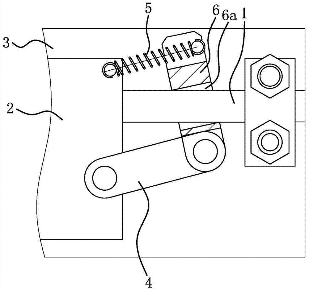
[0040] like figure 1 As shown, the linear guide rail 1 in the slider brake mechanism of the linear guide rail assembly is fixed on a base plate 3 .

[0041] like figure 1 As shown, the slider brake mechanism of the linear guide assembly includes a pull rod 4 , a tension spring 5 and a brake swing rod 6 .

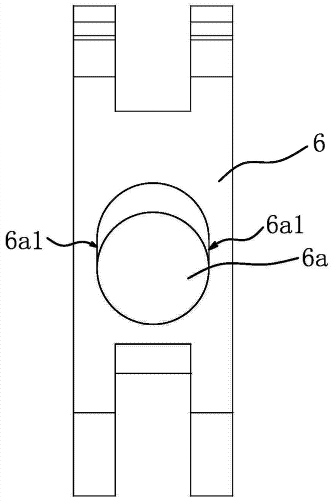
[0042] like figure 1 and figure 2 As shown, the brake rocker 6 has a snap-in hole 6a with two guide sides 6a1. The cross section of the linear guide 1 is circular, the cross section of the occlusal hole 6a is strip-shaped, the outer side of the linear guide 1 is dependent on the two guide sides 6a1, and the upper and lower sides of the occlusal hole 6a are arc-shaped.

[0043] The linear guide rail 1 passes through the occlusal hole 6a; the pull rod 4 and the brake swing rod 6 are both straight rods, one end of the pull rod 4 is hinged to the slider 2, and the other end of the pull rod 4 is hinged to one end of the brake swing rod 6; the tension spring 5 One end of the...

Embodiment 2

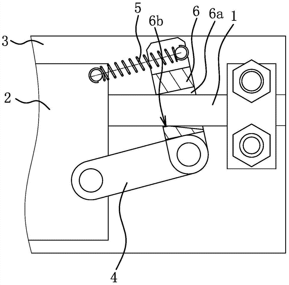
[0055] The structure and principle of this embodiment are basically the same as that of Embodiment 1, the difference is that: image 3 and Figure 4 As shown, the cross-section of the linear guide 1 is rectangular, and the cross-section of the bite hole 6a is also rectangular. The cross-sectional width of the bite hole 6a is the same as that of the linear guide 1. the cross-sectional length. The outer surface of the linear guide rail 1 and the two guiding side surfaces 6a1 are in one-to-one correspondence. There is an engaging tooth 6b on the lower side wall of the engaging hole 6a. Under the elastic force of the extension spring 5, the engaging tooth 6b and one end hole of the engaging hole 6a The edges and corners on the mouth all abut against the linear guide rail 1 to form a pre-occlusion.

Embodiment 3

[0057] The structure and principle of this embodiment are basically the same as that of Embodiment 1, the difference is that: Figure 7 As shown, the automatic unlocking mechanism includes an unlocking member 14 that is fixed on the lifting slider 9 and can push the other end of the brake swing lever 6 to swing. The unlocking part 14 is a cylinder or an electromagnet. Both the unlocking part 14 and the driving part 10 are electrically connected to controllers such as a PLC or a single-chip microcomputer. The controller first controls the action of the unlocking part 14, and after the unlocking part 14 pushes the other end of the brake lever 6 to swing to unlock, the controller then controls the driving part 10. Action, the driving part 10 drives the lifting slider 9 to move and realizes loosening the metal bar.


PUM


Abstract

The invention provides a slider brake mechanism of a linear guide rail assembly and a lifting device of a bar cutting machine, which respectively belong to the technical fields of machinery and machine tools and solve the problem of low flatness of a cross section of a metal bar. The structure-improved slider brake mechanism of the linear guide rail assembly comprises a pull rod, a tension spring and a brake swing rod with an occlusion hole; a linear guide rail penetrates through the occlusion hole of the brake swing rod; one end of a pull rod is hinged to a slider; the other end of the pull rod is hinged to one end of the brake swing rod; the bar cutting machine comprises a rack and a moving cutter die; the lifting device comprises the lifting slider, a driving part and two parallel linear guide rails and also comprises the tension spring and the brake swing rod with the occlusion hole. The structure-improved slider brake mechanism of the linear guide rail assembly is simple in structure and convenient to operate and control, and the lifting device of the bar cutting machine is fast in response, is capable of bearing larger external action force and is very suitable for popularization.

Description

technical field [0001] The invention belongs to the technical field of machinery, and relates to a braking device, in particular to a sliding block braking mechanism of a linear guide rail assembly. [0002] The invention belongs to the technical field of machine tools, and relates to a bar cutting machine, in particular to a lifting device of the bar cutting machine. Background technique [0003] The slider brake mechanism of the linear guide rail assembly is a mechanism that stops the slider and the mechanism carried on the slider on the linear guide rail according to the needs. The traditional brake mechanism, such as the slider, is tightened by bolts; the traditional brake mechanism has problems such as cumbersome operation. [0004] For this reason, someone has proposed a braking device of a linear guide rail and recorded it in the Chinese patent literature. Its application number is 201320335104.9, and the authorized announcement number is CN203304906U; Make the two ...

Claims


Application Information

Patent Timeline
Patent Type & Authority Patents(China)
IPC IPC(8): B23Q3/00B23D33/02
CPCB23D33/02B23Q3/064B23Q3/08B23Q3/082B23Q2703/04
Inventor 马文强
Owner 台州市良曜成套设备有限公司
Why Eureka
Try Eureka