Pneumatic rotary clamping device
A technology of clamping device and rotating structure, applied in the direction of clamping device, positioning device, clamping, etc., can solve the problems of reducing the strength of the piston rod, easy to break the piston rod, etc. Effect
- Summary
- Abstract
- Description
- Claims
- Application Information
AI Technical Summary
Problems solved by technology
Method used
Image

Examples
Embodiment 1
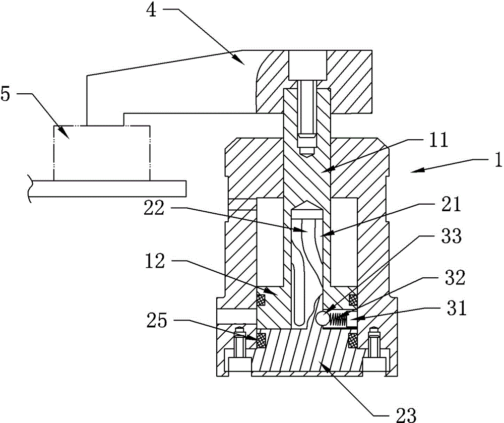
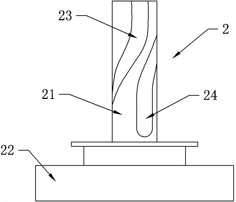
[0014] A pneumatic rotary clamping device, comprising a cylinder 1 and a pressing arm 4, the pressing arm 4 is connected to the piston rod 11 of the cylinder 1 through bolts, wherein a rotating structure located in the cylinder 1 is also provided, and the rotating structure includes an integrally connected base 23 and the spindle 21, the longitudinal section of the base 23 is in the shape of a boss, the flange on the base 23 is connected to the cylinder 1 by bolts, and a sealing ring 25 is arranged between the base 23 and the inner wall of the cylinder 1, and the spindle 21 is axially upward A spiral groove 22 is provided, and the mandrel 21 coaxially slides and fits with the piston rod 11 from the side of the piston seal 12 of the cylinder 1 . The piston seal 12 of the cylinder 1 is provided with a guide structure matching the spiral groove 22 .
[0015] In this embodiment, the guide structure includes a spring seat 31, a compression spring 32 and a steel ball 33. One end of t...
Embodiment 2
[0019] The difference from Embodiment 1 is that the guiding structure includes a mounting seat and a guide pin that can cooperate with the spiral groove 22. One end of the guide pin is connected to the mounting seat, and the mounting seat is connected to the piston seal 12 of the cylinder 1. The guide pin guiding structure is simpler .
[0020] Specific use process:
[0021] Taking Example 1 as an example, such as figure 1 As shown, the clamping of the workpiece 5 by the downward movement of the pressing arm 4 is taken as an example for illustration, and the figure shows the state of clamping the workpiece 5 . The air hole in the lower part of the cylinder 1 intakes air. At this time, the piston seal 12 of the cylinder 1 moves upward, and the steel ball of the guiding structure in the piston seal 12 first moves upward along the linear groove 24 on the mandrel 21. When it moves to the spiral groove 22, The steel ball slides with the spiral groove 22. At this time, the piston ...
PUM
 Abstract
Description
Claims
Application Information
 - R&D
- Intellectual Property
- Life Sciences
- Materials
- Tech Scout
- Unparalleled Data Quality
- Higher Quality Content
- 60% Fewer Hallucinations
Browse by: Latest US Patents, China's latest patents, Technical Efficacy Thesaurus, Application Domain, Technology Topic, Popular Technical Reports.
© 2025 PatSnap. All rights reserved.Legal|Privacy policy|Modern Slavery Act Transparency Statement|Sitemap|About US| Contact US: help@patsnap.com