
Four-axis multi-directional hydraulic fixture and clamping method implemented by same

A hydraulic fixture and multi-directional technology, applied in the field of tooling and fixtures, can solve the problems of uncontrollable workpiece size, mass production, and increased number of tooling, and achieve the effects of good neutrality, compact device structure, and reasonable layout

Inactive Publication Date: 2015-01-28
安徽精科机器有限公司
View PDF9 Cites 2 Cited by
  • Summary
  • Abstract
  • Description
  • Claims
  • Application Information

AI Technical Summary

Problems solved by technology

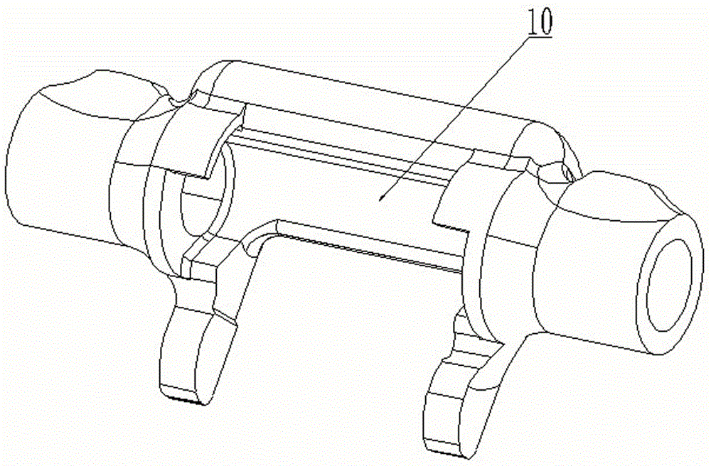
[0002] In the field of mechanical processing, it is often necessary to perform deep processing on various parts of workpieces with different shapes. figure 1 Shown is a clutch release fork for a truck. After the overall casting is completed, it is necessary to process multiple parts such as the body, the fork legs, the inner shaft hole of the body, and the counterbore at the top. There are many processing procedures and there are physical and position requirements. The workpiece is

Method used


Image

  • Four-axis multi-directional hydraulic fixture and clamping method implemented by same
  • Four-axis multi-directional hydraulic fixture and clamping method implemented by same
  • Four-axis multi-directional hydraulic fixture and clamping method implemented by same

Examples


Example Embodiment

[0019] Example one

[0020] Such as figure 1 It can be seen that this embodiment is mainly applied to the clamping of the clutch release fork 10 for trucks.

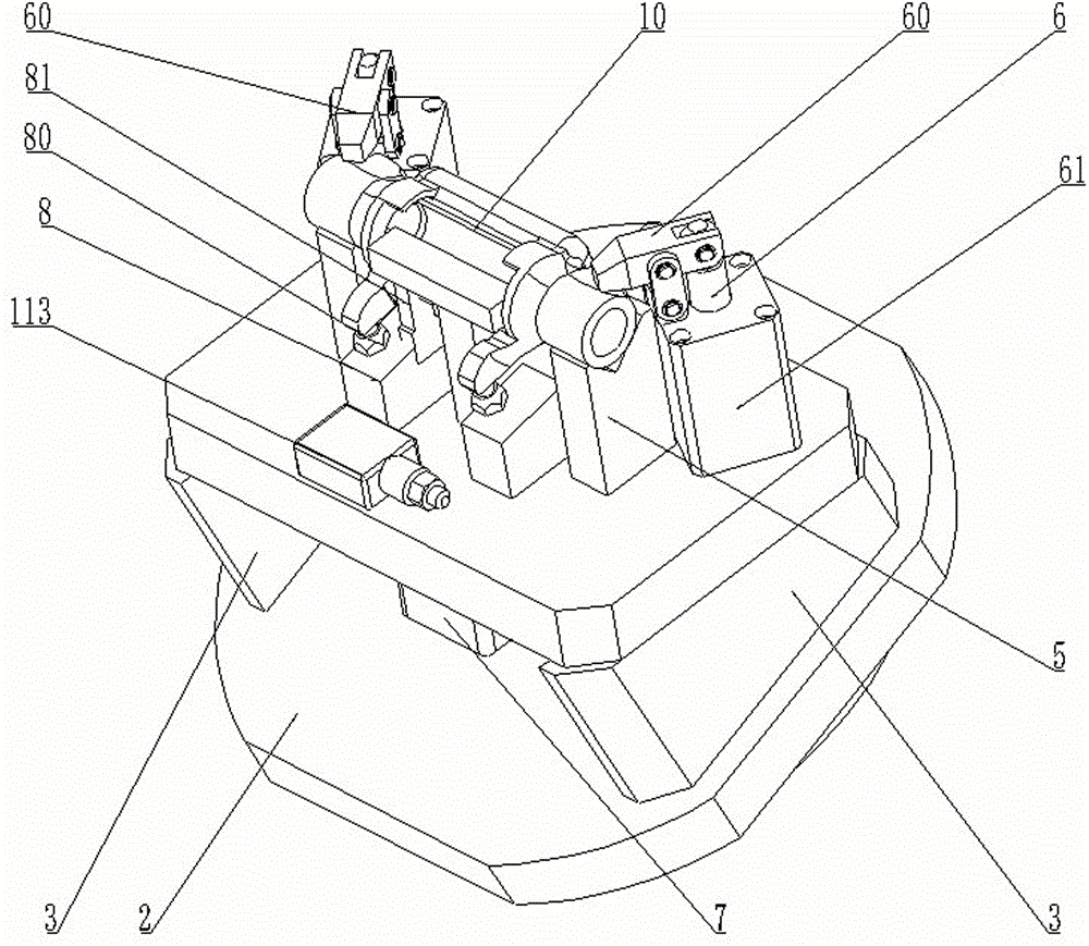
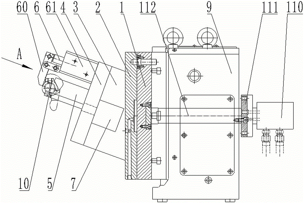
[0021] Such as Figure 2 to Figure 5 It can be seen that the four-axis multi-directional hydraulic clamp of the present invention includes a mounting flange 1, on which a transition disc 2 is fixed, and two right-angle trapezoidal structures are symmetrically provided on the transition disc 2 The two transition blocks 3 are fixedly provided with a bottom plate 4, the bottom plate 4 is fixed with two V-shaped blocks 5 symmetrically along the center line, and the bottom plate 4 is also provided with two lever cylinders 6, which are 6 is fixed on the bottom plate 4 by an oil cylinder backing plate 61; the levers 60 of the two lever cylinders 6 are matched with the two V-shaped blocks 5 respectively; it also includes an auxiliary compression hydraulic cylinder 7 arranged in the middle of the transition disc 2, The end of the pi...


PUM


Abstract

The invention provides a four-axis multi-directional hydraulic fixture. The four-axis multi-directional hydraulic fixture is characterized in that a transition disc is fixed onto a mounting flange of the four-axis multi-directional hydraulic fixture, a bottom plate is arranged on the transition disc via two transition blocks which are of right trapezoid structures, two V-shaped blocks are symmetrically fixed onto the bottom plate along the center line of the bottom plate, and two lever cylinders are further arranged on the bottom plate; the four-axis multi-directional hydraulic fixture further comprises an auxiliary compressing oil pressure cylinder and a hydraulic pipeline, the auxiliary compressing oil pressure cylinder is arranged in the middle of the transition disc, and a compressing plate is arranged at the tail end of a piston rod of the auxiliary compressing oil pressure cylinder; the hydraulic pipeline comprises an oil pressure sequence valve which are connected with the two lever cylinders and the auxiliary compressing oil pressure cylinder. Two auxiliary positioning devices are symmetrically arranged between the two V-shaped blocks on the bottom plate and comprise auxiliary positioning bases, the auxiliary positioning bases are arranged on the bottom plate, and limiting screws with adjustable heights are arranged on the upper end surfaces of the auxiliary positioning bases. A limiting plate is arranged on the upper end surface of at least one auxiliary positioning base. The four-axis multi-directional hydraulic fixture has the advantages that components can be firmly and reliably clamped by the four-axis multi-directional hydraulic fixture and can be machined in multiple working procedures by the aid of the same tool.

Description

technical field [0001] The invention relates to a tooling fixture for auto parts, in particular to a tooling fixture applied on four axes of a numerical control machining center. Background technique [0002] In the field of mechanical processing, it is often necessary to perform deep processing on various parts of workpieces with different shapes. figure 1 Shown is a clutch release fork for a truck. After the overall casting is completed, it is necessary to process multiple parts such as the body, the fork legs, the inner shaft hole of the body, and the counterbore at the top. There are many processing procedures and there are physical and position requirements. The workpiece is positioned and clamped with multiple fixtures. Since the positioning reference of each tool is different, the positioning and pressing point will also change. The conversion of the reference and the difference in the pressing point will lead to the uncontrollable size of the workpiece during the pro...

Claims


Application Information

Patent Timeline
IPC IPC(8): B23Q3/08
CPCB23Q3/082
Inventor 杨建勇黄瑾王芳杜凤玲余花妮周家彬周汪军陈义红
Owner 安徽精科机器有限公司
Learn More