
Protecting cover structure for machining equipment

A technology of mechanical processing and protective cover, which is applied in the direction of metal processing equipment, metal processing machinery parts, manufacturing tools, etc., which can solve the problems of reducing the size, increasing the area occupied by a single device, and increasing the working space of the protective device.

Inactive Publication Date: 2015-01-28
FOSHAN TIANJIAN MECHANICAL CO LTD
View PDF4 Cites 2 Cited by
  • Summary
  • Abstract
  • Description
  • Claims
  • Application Information

AI Technical Summary

Problems solved by technology

For the traditional protective device structure that adopts side-shifting and flat-drawing, the two sides of the frame need to be preset with moving tracks and spaces for the protective device to move sideways and pull horizontally to both sides, thus increasing the use of this structural form. In the working space of the protective device, the floor area of ​​a single piece of equipment becomes larger, which is not conducive to the reduction of the cost of the processing manufacturer.

Method used


Image

  • Protecting cover structure for machining equipment
  • Protecting cover structure for machining equipment
  • Protecting cover structure for machining equipment

Examples


Embodiment Construction

[0020] The present invention will be further described below in conjunction with specific embodiment:

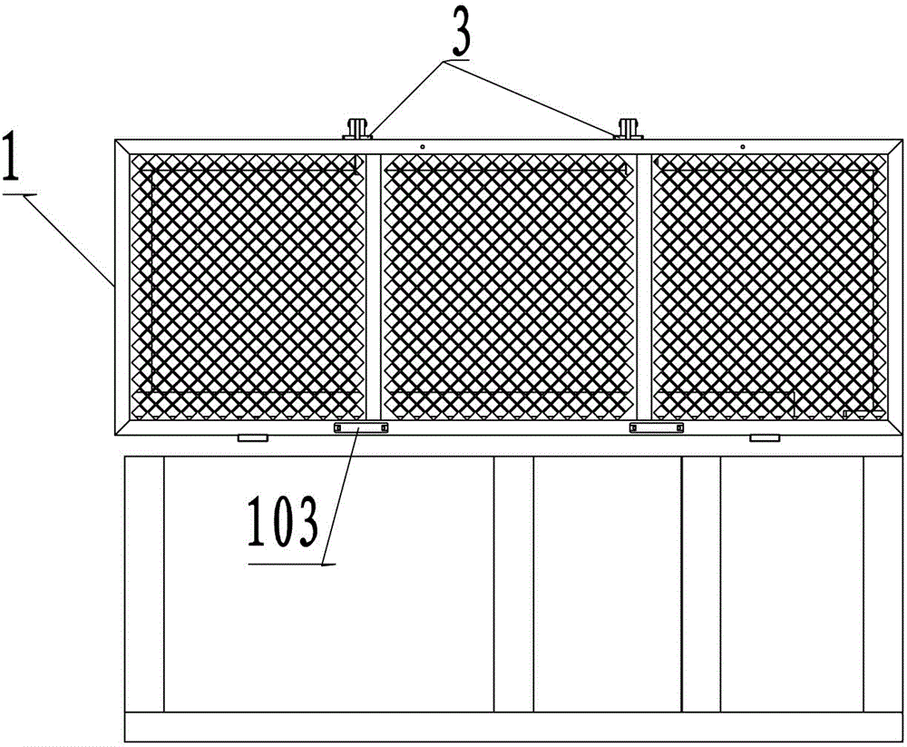
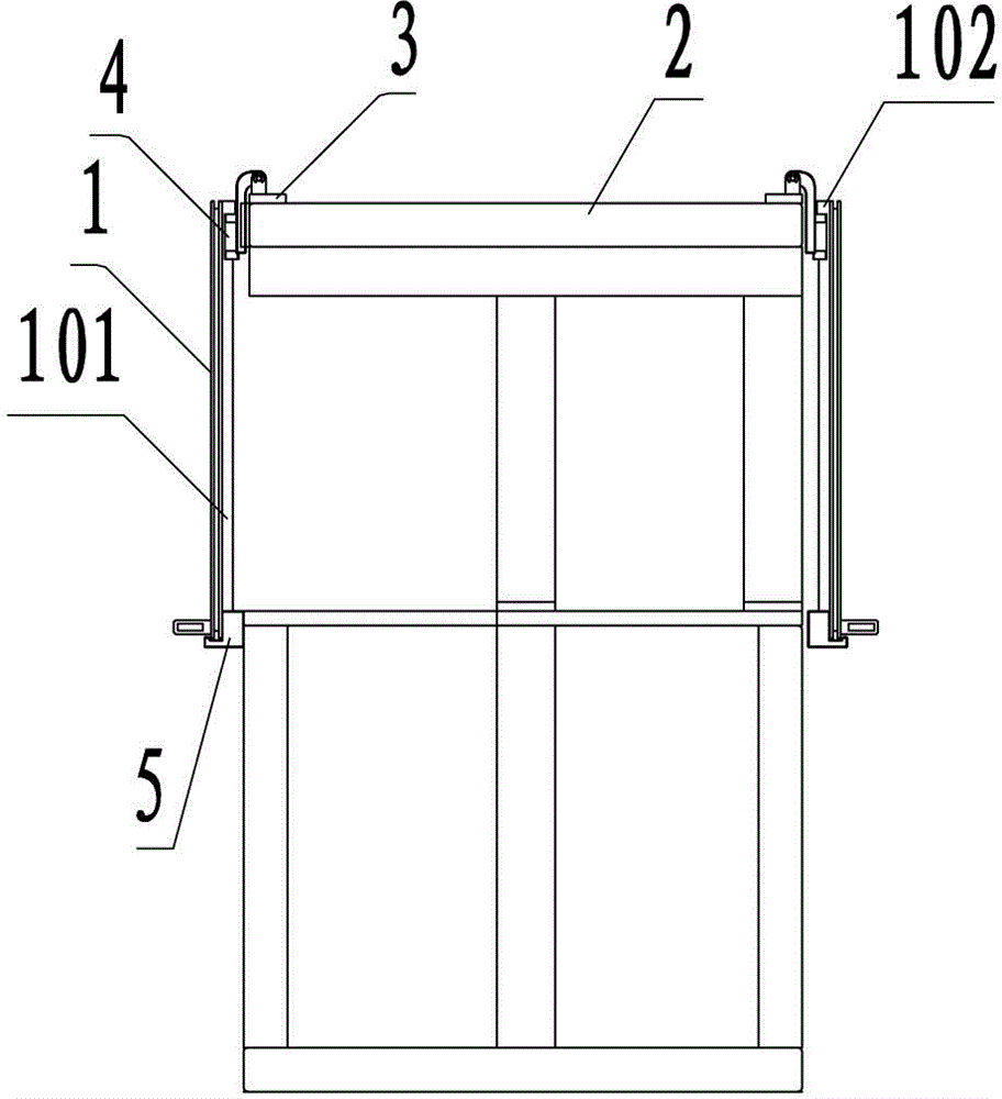
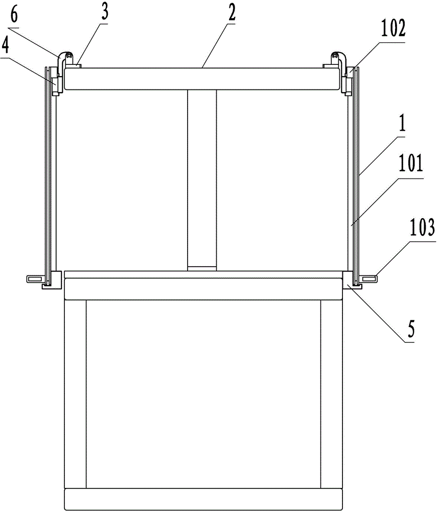
[0021] See attached figure 1 to attach image 3 As shown, what is described in this embodiment is a protective cover structure used on machining equipment. In this embodiment, the protective cover structure is installed on the front and rear sides of the mechanical processing equipment, wherein the protective cover structure includes as The protective part 1 of the main body, the fixed support 3 fixed on the top of the frame 2, the slider 4 and the protective part bracket 5. The protective part 1 can be made of tempered glass or a metal safety net, preferably a safety net. The inner side of the main body of the aluminum alloy frame of the safety protection net is vertically fixed with a guide rail 101, and the safety protection net forms a sliding connection with the slider 4 through the guide rail 101 on it, wherein the slider 4 is installed by a hinge slider The flange ...


PUM


Abstract

The invention provides a protecting cover structure for machining equipment. The protecting cover structure comprises protection parts provided with handles, fixed supporting seats fixedly mounted at the top end of a machine frame, sliding blocks and protection part supporting blocks mounted on the machine frame, wherein the sliding blocks are hinged and connected to the fixed supporting seats; the protection parts and the sliding blocks are connected in a sliding manner through guide rails which are vertically mounted on the inner side of a framework of the protection parts; and when the protection parts are in a closed state, the lower ends of the protection parts and the protection part supporting are in clamping fit. The protecting cover structure is simple, and is conveniently operated by operating staff. When the protecting cover structure is mounted, under the condition that the equipment operates normally is ensured, the occupied space for mounting of the equipment can be effectively reduced, and the production cost of manufacturing and production enterprises is greatly reduced.

Description

technical field [0001] The invention relates to the technical field of installation protection structures on machining equipment, in particular to a protective cover structure used on machining equipment. Background technique [0002] During the operation of mechanical processing equipment, for the personal safety of on-site operators, it is usually necessary to install protective devices to close the processing part. For the traditional protective device structure that adopts side-shifting and flat-drawing, the two sides of the frame need to be preset with moving tracks and spaces for the protective device to move sideways and pull horizontally to both sides, thus increasing the use of this structural form. In the working space of the protective device, the footprint of a single piece of equipment becomes larger, which is not conducive to the reduction of the cost of the processing manufacturer. Contents of the invention [0003] The purpose of the present invention is t...

Claims


Application Information

Patent Timeline
IPC IPC(8): B23Q11/08
CPCB23Q11/08
Inventor 黄伟明
Owner FOSHAN TIANJIAN MECHANICAL CO LTD
Learn More