
Cutting device for manufacturing of LED (light emitting diode) kits and LED kit automatic assembly machine

A technology of cutting device and cutting mechanism, which is applied in the direction of cutting device with nibbling effect, shearing device, device for coating liquid on the surface, etc. It can solve the problems of difficult handling and welding, exposed pins of LED lights, Safety hazards and other issues

Active Publication Date: 2015-01-28
NINGBO SUNPU OPTO SEMICON
View PDF8 Cites 15 Cited by
  • Summary
  • Abstract
  • Description
  • Claims
  • Application Information

AI Technical Summary

Problems solved by technology

[0004] 2. The pins of the LED light are directly welded on the external circuit board, which will cause the pins of the LED light to be easily bent or broken by foreign objects
[0005] 3. The size of LED lamps is usually small, and it is not easy to handle and weld, which will affect the accuracy of welding and cause an increase in the rate of defective products
[0006] 4. The pins of the LED light are directly welded on the external circuit board, which may easily cause the pins of the LED light to be exposed, which will cause certain safety hazards
At present, these processes in the production and manufacture of LED kits are still operated purely manually. In this way, the operator will feel a certain degree of fatigue during long hours of work, resulting in low production efficiency. On the other hand, it is easy to cause cutting The lengths of the LED lamp pins are different, the glue is prone to overflow or lack of glue when dispensing, and the LED lamp and plastic parts are not fixed firmly enough, which greatly affects the quality of the LED kit.

Method used

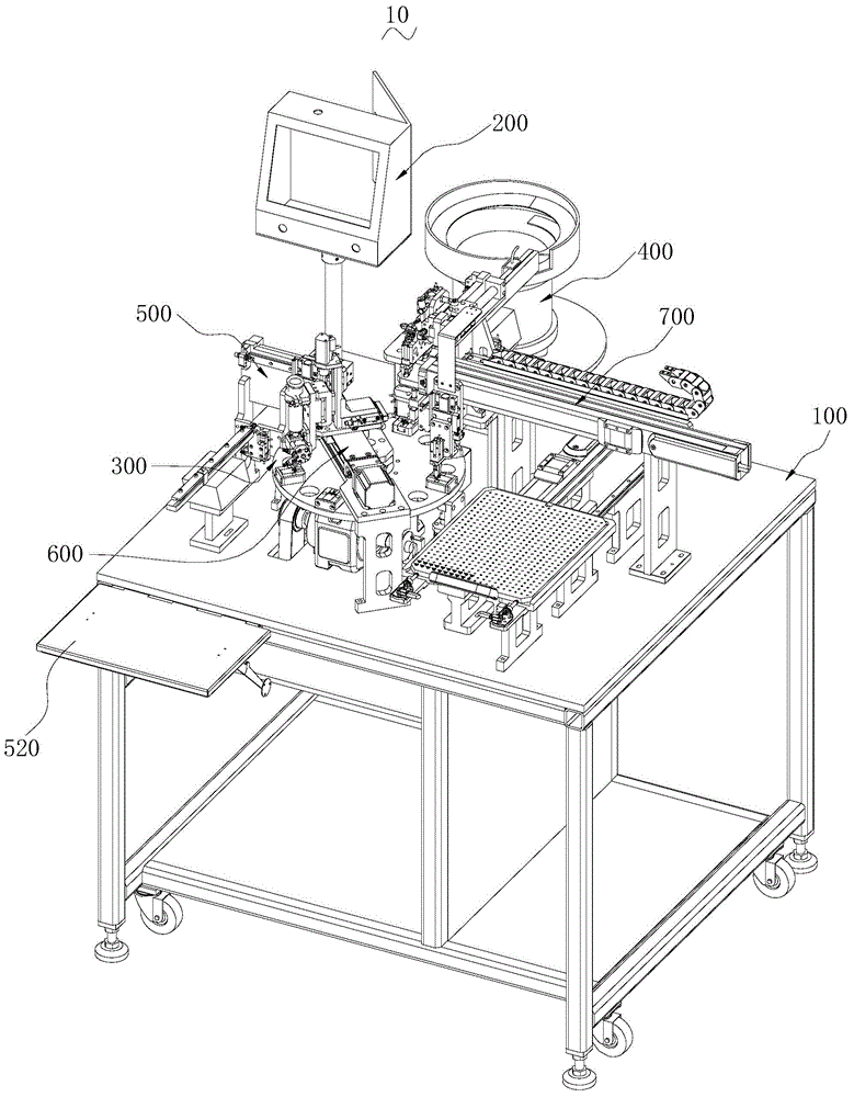
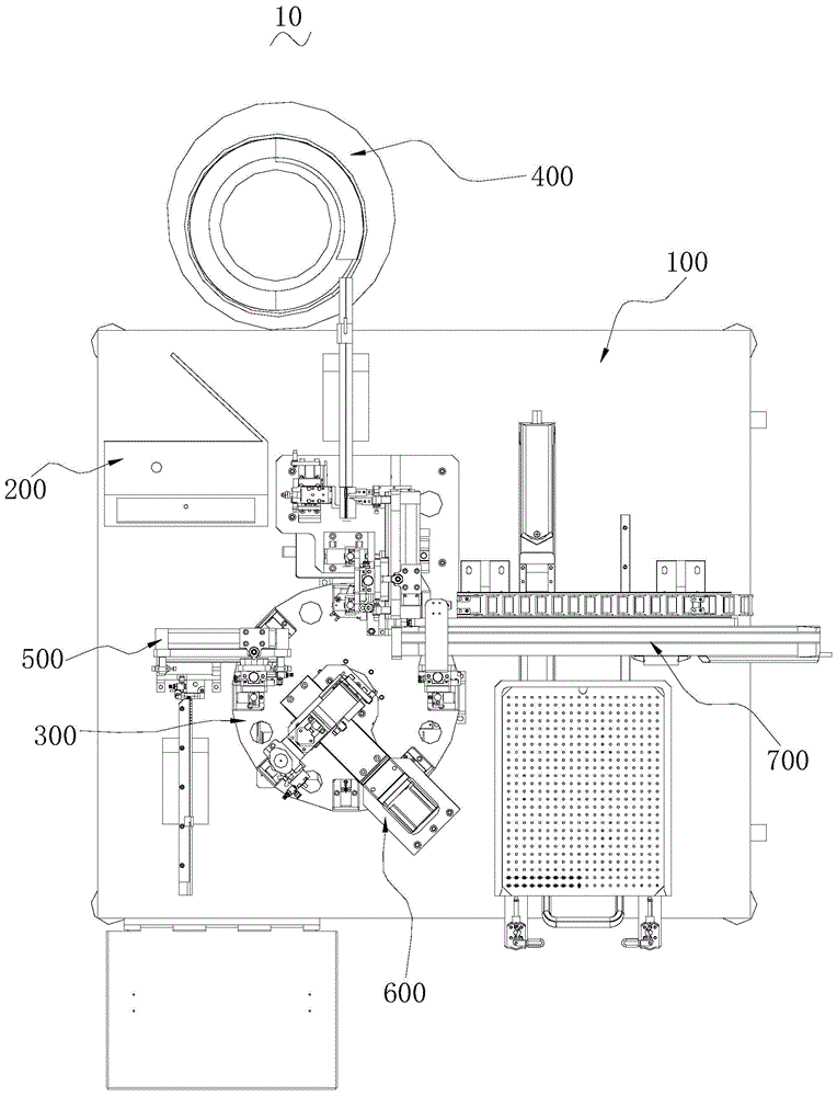
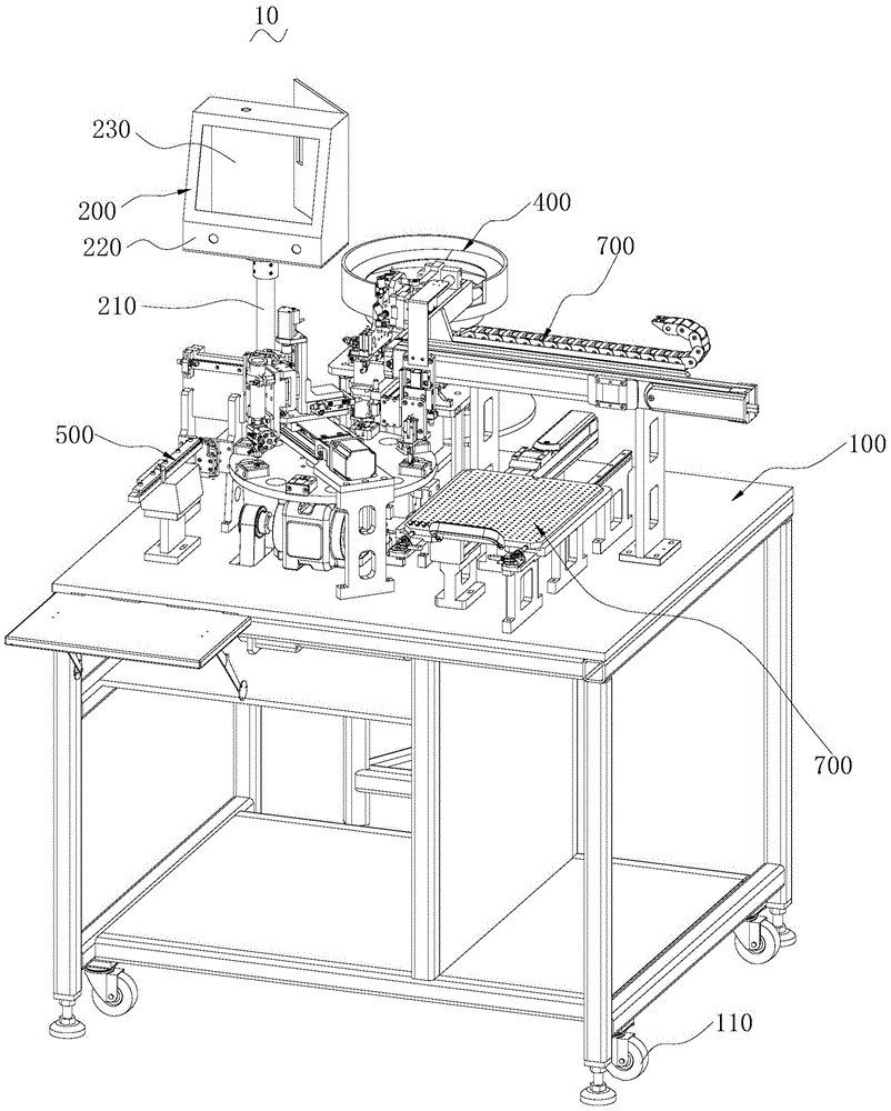

Image

  • Cutting device for manufacturing of LED (light emitting diode) kits and LED kit automatic assembly machine
  • Cutting device for manufacturing of LED (light emitting diode) kits and LED kit automatic assembly machine
  • Cutting device for manufacturing of LED (light emitting diode) kits and LED kit automatic assembly machine

Examples


Embodiment Construction

[0031] In order to facilitate the understanding of the present invention, the present invention will be described more fully below with reference to the associated drawings. Preferred embodiments of the invention are shown in the accompanying drawings. However, the present invention can be embodied in many different forms and is not limited to the embodiments described herein. On the contrary, the purpose of providing these embodiments is to make the disclosure of the present invention more thorough and comprehensive.

[0032] It should be noted that when an element is referred to as being “fixed” to another element, it can be directly on the other element or there can also be an intervening element. When an element is referred to as being "connected to" another element, it can be directly connected to the other element or intervening elements may also be present. The terms "vertical," "horizontal," "left," "right," and similar expressions are used herein for purposes of ill...


PUM


Abstract

The invention relates to a cutting device for manufacturing of LED (light emitting diode) kits and an LED kit automatic assembly machine. The cutting device comprises a bracket, a material vibration mechanism, a material shifting mechanism, a cutting mechanism, a material fetching mechanism and a waste box, wherein the bracket is arranged on a worktable, the material vibration mechanism is arranged on the bracket, the material shifting mechanism is arranged at one side, near the material vibration mechanism, of the bracket, the cutting mechanism is arranged on the bracket and is arranged near the material vibration mechanism, the material fetching mechanism is arranged on the bracket and is arranged near the cutting mechanism, and an opening of the waste box faces the cutting mechanism. The cutting device for manufacturing of the LED kits has the advantages that only an LED lamp is arranged in a material vibration cylinder by an operator, then the LED lamp in the material vibration cylinder is arranged on a material vibration plate, and one part of pins of the LED lamp can be cut off; compared with the traditional manual operation method, the production efficiency is higher, and the product quality is also higher.

Description

technical field [0001] The invention relates to the field of automatic mechanized equipment, in particular to a cutting device for manufacturing LED kits and an automatic assembly machine for LED kits. Background technique [0002] At present, in the process of soldering LED lamps to external circuit boards, the practice of directly soldering LED lamps to external circuit boards is usually not adopted, the reasons are: [0003] 1. The lengths of the pins of different LED lights are different. For circuit boards of different specifications, the length of the pins needs to be adjusted adaptively. For example, some pins of LED lights are cut to make them suitable for circuit boards of different specifications. [0004] 2. The pins of the LED light are directly welded on the external circuit board, which will cause the pins of the LED light to be easily bent or broken by collisions with foreign objects. [0005] 3. The size of LED lamps is usually small, and it is difficult to ...

Claims


Application Information

Patent Timeline
IPC IPC(8): F16B11/00B23D27/00B05C5/00B05C11/10
CPCB05C5/00B05C11/10B23D27/00F16B11/00
Inventor 吴长江
Owner NINGBO SUNPU OPTO SEMICON
Learn More