
Head-mounted display

A display and head-mounted technology, applied in the field of head-mounted displays, can solve the problems of non-adjustable center distance and inability to adapt to the needs of use, so as to achieve the effect of improving versatility and market competitiveness

Active Publication Date: 2015-01-28
GEER TECH CO LTD
View PDF5 Cites 51 Cited by
  • Summary
  • Abstract
  • Description
  • Claims
  • Application Information

AI Technical Summary

Problems solved by technology

[0003] In the prior art, a head-mounted display usually includes a main body frame, a display panel (display screen) fixed on the front side of the main frame, and left and right lens barrels with lenses inside, wherein the left and right lens barrels are connected to the The main frame is an integral structure, located on the back side of the main frame, and cannot be moved. Correspondingly, the center distance of the left and right lenses, the distance between the left and right lenses and the display panel are fixed and cannot be adjusted, so that the product cannot be well displayed. Adapt to the needs of users with various vision conditions

Method used


Image

  • Head-mounted display
  • Head-mounted display
  • Head-mounted display

Examples


Embodiment 1

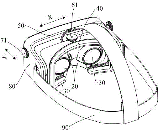
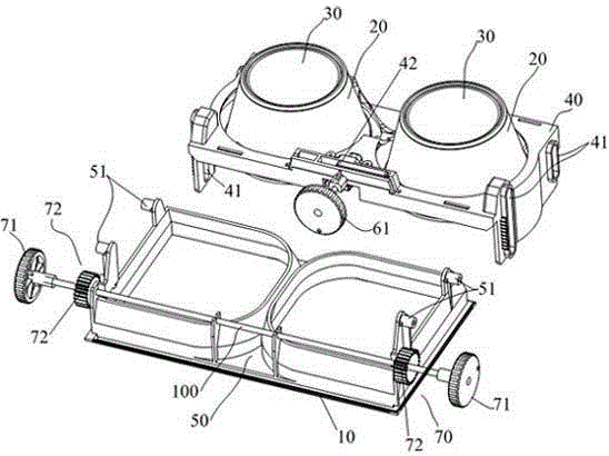
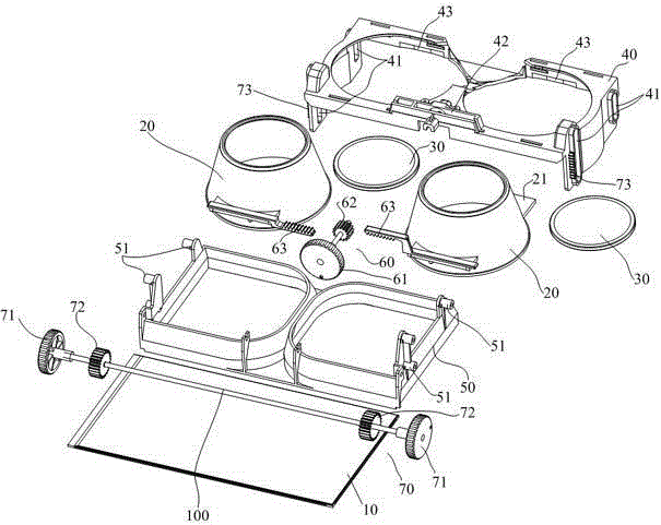
[0017] combine figure 1 , figure 2 , while referring to Figure 3 to Figure 5 In this embodiment, the left and right ends of the X-axis support 40 are provided with first guide grooves 41, and the Y-axis support 50 is correspondingly provided with a first slide rail 51 embedded in the first guide grooves 41, thereby realizing the X-axis support 40 Slip-fit ​​assembly with Y-axis bracket 50. In order to reduce friction during relative sliding, the first slide rail in this embodiment is a cylindrical slide rail arranged horizontally, and the inner surface of the first guide groove 41 has a smooth transition.

[0018] Additionally, if Figure 4 and Figure 5 As shown, the X-axis adjustment assembly 60 in this embodiment includes an X-axis adjustment handwheel 61, an X-axis transmission gear 62, and an X-axis transmission rack 63 respectively arranged on the two lens barrels 20. The X-axis adjustment handwheel 61 and The X-axis transmission gear 62 is coaxially arranged, and...

Embodiment 2

[0025] In this embodiment, the X-axis adjustment assembly 60 and the Y-axis adjustment assembly 70 are adjusted by belt pulley transmission, but the adjustment is not as precise as the rack and pinion transmission.


PUM


Abstract

The invention provides a novel head-mounted display capable of perfectly adapting to the use of users in different vision situations and different pupil distances and accordingly improving the versatility. The head-mounted display comprises a body frame, a display panel, a left lens barrel provided with a lens and a right lens barrel provided with a lens. The body frame comprises an X-axis bracket and Y-axis bracket. The lens barrels slide in the X-axis direction and are arranged on the X-axis bracket. The head-mounted display further comprises an X-axis adjustment assembly and a Y-axis adjustment assembly. The X-axis adjustment assembly is operated to enable the two lens barrels to slide in the X-axis direction on the X-axis bracket to further adjust the center-to-center spacing between the two lenses, the Y-axis adjustment assembly is operated to enable the X-axis bracket to slide opposite to the Y-axis bracket in the Y-axis direction to further adjust the fore-and-aft spacing between the two lenses and the display panel, so that a user can easily adjust the positions of the lenses according to the pupil distance and the vision situation of the user. Therefore, the versatility of the head-mounted display is improved, and accordingly the market competitiveness of the head-mounted display is enhanced.

Description

technical field [0001] The invention relates to a head-mounted display, in particular to a head-mounted display capable of adjusting the distance between the centers of two lenses and the distance between the lens and a display panel so that it can be well adapted to users with different pupil distances and different vision conditions. Background technique [0002] Head Mount Display (Head Mount Display) is a device for displaying images and colors, usually in the form of a goggle or a helmet, which puts the display close to the user's eyes, and adjusts the focal length through the optical path to project images to the eyes at a close distance. [0003] In the prior art, a head-mounted display usually includes a main body frame, a display panel (display screen) fixed on the front side of the main frame, and left and right lens barrels with lenses inside, wherein the left and right lens barrels are connected to the The main frame is an integral structure, located on the back ...

Claims


Application Information

Patent Timeline
IPC IPC(8): G02B27/01
CPCG02B27/0176
Inventor 陈锦灿刘敏
Owner GEER TECH CO LTD
Learn More