
Hall effect based double-digital-display simple pendulum period high-accuracy synchronous measuring device

A technology of high-precision synchronization and single pendulum period, which is applied in the research field of middle school physics teaching aids. It can solve the problems of damping and inability to display the vibration time or frequency of vibration synchronously, and achieve the effects of strong operability, difficult synchronization display and strong practicability.

Inactive Publication Date: 2015-01-28
郭金虎
View PDF7 Cites 5 Cited by
  • Summary
  • Abstract
  • Description
  • Claims
  • Application Information

AI Technical Summary

Problems solved by technology

[0002] CN202306904U discloses a high-precision measuring device for measuring the period of a single pendulum. It utilizes a reed switch to do a magnetic sensor, and utilizes a single-chip microcomputer to intelligently measure the vibration frequency and time of a single pendulum. It has two major defects: the one is to use a reed switch as a magnetic sensor, Because the magnet encounters the magnetization of the reed reed, it produces magnetic resistance, so what the pendulum does is to damp the vibration; second, the single-chip microcomputer processes data, and can only display one of the vibration time or vibration times on the display screen, which cannot be synchronized To display the vibration time or the number of vibrations, it is necessary to design a single pendulum period measuring device with dual display screens that simultaneously display the vibration time and the number of vibrations, and the display circuits are required to be independent of each other without interfering with each other

Method used


Image

  • Hall effect based double-digital-display simple pendulum period high-accuracy synchronous measuring device
  • Hall effect based double-digital-display simple pendulum period high-accuracy synchronous measuring device

Examples


Embodiment Construction

[0009] Further detailed description is given below through examples.

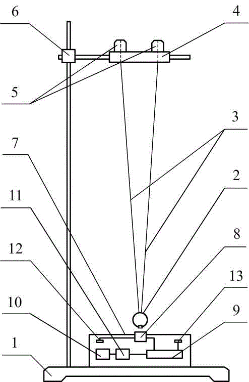
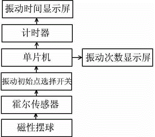
[0010] like figure 1 , figure 2 As shown, a high-precision synchronous measuring device with double digital display and single pendulum period based on Hall effect, including iron stand 1, magnetic pendulum ball 2, double cycloid 3, pendulum length regulator 4, adjustment knob 5, and iron stand clamp 6. Electric control box 7; there is a small magnet under the magnetic pendulum ball 2, and the pendulum length regulator 4 is connected to the upper part through the double cycloid 3, and the pendulum length regulator 4 adjusts the double cycloid 3 through two adjustment knobs 5 The length of the pendulum, and the length of the cycloid is positioned by the positioning clip, and it will not loosen; the pendulum length regulator 4 is fixed on the iron stand 1 through the adjustment knob 5; the electric control box 7 includes a Hall sensor 8, a single-chip microcomputer 9, Time display screen 10, times display ...


PUM


Abstract

A hall effect based double-digital-display simple pendulum period high-accuracy synchronous measuring device comprises a magnetic pendulum ball, double pendulum lines and an electric control box; a small magnet is arranged below the magnetic pendulum ball; a pendulum length adjuster is connected above the magnetic pendulum ball through the double pendulum lines; the pendulum length adjuster adjusts the pendulum length of two adjusting knobs; the electric control box comprises a hall sensor, a single chip microcomputer, a time display screen, a frequency display screen, a vibration initial point selection switch and a main power source switch; two display circuits are mutually independent and not interfered due to the fact that a timer is in an independent design. The hall effect based double-digital-display simple pendulum period high-accuracy synchronous measuring device has the advantages of not generating magnetic resistance and being high in sensitivity due to the fact that a timing starting point is selected according to a simple pendulum magnetic pendulum ball position detected by the hall sensor; well solving the problem that the single chip microcomputer is difficult to display due to the facts that one display screen is used for recording the vibration time and the other display screen is used for displaying the vibration times and display is synchronous; being intellectual, practical and interesting.

Description

technical field [0001] The invention relates to the research field of middle school physics teaching aids, in particular to a Hall-effect-based high-precision synchronous measuring device for double-digit display and single-pendulum periods. Background technique [0002] CN202306904U discloses a high-precision measuring device for measuring the period of a single pendulum. It utilizes a reed switch to do a magnetic sensor, and utilizes a single-chip microcomputer to intelligently measure the vibration frequency and time of a single pendulum. It has two major defects: the one is to use a reed switch as a magnetic sensor, Because the magnet encounters the magnetization of the reed reed, it produces magnetic resistance, so what the pendulum does is to damp the vibration; second, the single-chip microcomputer processes data, and can only display one of the vibration time or vibration times on the display screen, which cannot be synchronized To display the vibration time or the n...

Claims


Application Information

Patent Timeline
IPC IPC(8): G09B23/10
CPCG09B23/10
Inventor 郭金虎
Owner 郭金虎
Learn More