
A flexible parallel platform device

A platform device and platform technology, applied in the field of robot micro-operation, can solve problems such as inability to achieve high precision and larger workspace requirements, and achieve the effects of avoiding errors, compact mechanism structure, and eliminating the influence of mechanism accuracy.

Active Publication Date: 2016-01-27
HARBIN INST OF TECH
View PDF8 Cites 2 Cited by
  • Summary
  • Abstract
  • Description
  • Claims
  • Application Information

AI Technical Summary

Problems solved by technology

[0003] The purpose of the present invention is to solve the problem that the existing flexible hinge cannot achieve high precision and larger working space requirements in the micro-operation environment

Method used


Image

  • A flexible parallel platform device
  • A flexible parallel platform device

Examples


specific Embodiment approach 1

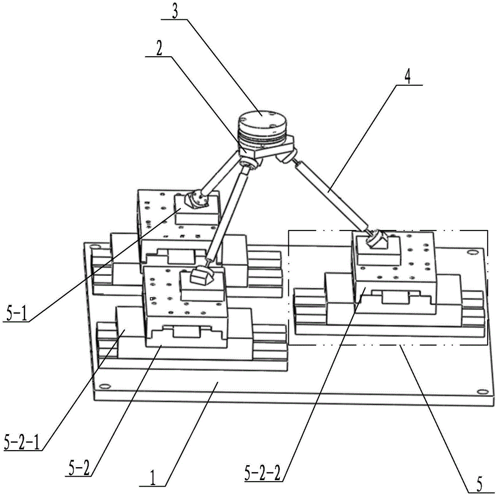
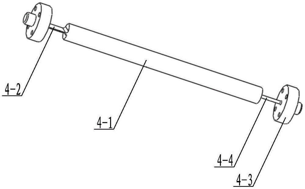
[0012] Specific implementation mode one: combine figure 1 and figure 2 Describe this embodiment, a flexible parallel platform device of this embodiment includes a shock-isolation platform 1, an upper platform 2, a six-dimensional force sensor 3, three flexible branch chains 4 and three sets of platform assemblies 5, and the three sets of platform assemblies 5 are installed on On the isolation platform 1, the upper platform 2 is located above the three sets of platform components 5, each set of platform components 5 and the lower end surface of the upper platform 2 are connected by a flexible branch chain 4, and the six-dimensional force sensor 3 is installed on the upper platform 2, each group of platform components 5 includes a base 5-1 and a piezoelectric drive motor 5-2, and the base 5-1 is installed on the upper end of the piezoelectric drive motor 5-2.

[0013] The upper platform 2 of this embodiment is fixed with a six-dimensional force sensor 3, which can detect the c...

specific Embodiment approach 2

[0014] Specific implementation mode two: combination figure 1 and figure 2 The present embodiment will be described. The piezoelectric drive motor 5 - 2 of the present embodiment is a piezoelectric ceramic drive motor. Such setting is convenient to ensure that the present invention has the advantages of high displacement precision of sub-nanometer level, high frequency response of tens of kHz, high reliability and small mechanism structure. Other compositions and connections are the same as in the first embodiment.

specific Embodiment approach 3

[0015] Specific implementation mode three: combination figure 1 and figure 2 To illustrate this embodiment, the included angles between two adjacent flexible branch chains 4 among the three flexible branch chains 4 of this embodiment are both 120°. Such setting can effectively utilize the space, and at the same time make the three branch chains at the same initial position, avoiding the occurrence of singular structures and failures caused by excessive local deformation. Other compositions and connections are the same as those in Embodiment 1 or Embodiment 2.


PUM


Abstract

The invention discloses a flexible parallel platform device, relates to a parallel platform device, and aims to solve the problem of incapability of meeting the requirements of high precision and larger working space in a micro operation environment in the conventional flexible hinge. The flexible parallel platform device comprises a shock isolation platform (1), an upper platform (2), a six-dimensional force sensor (3), three flexible branch chains (4) and three groups of platform assemblies (5), wherein the three groups of platform assemblies (5) are arranged on the shock isolation platform (1); the upper platform (2) is positioned above the three groups of platform assemblies (5); each group of platform assemblies (5) is connected with the lower end face of the upper platform (2) through one flexible branch chain (4); the six-dimensional force sensor (3) is arranged at the upper end of the upper platform (2); each group of platform assemblies (5) comprises a base (5-1) and a piezoelectric driving motor (5-2); the bases (5-1) are arranged at the upper ends of the piezoelectric driving motors (5-2). The flexible parallel platform device is applied to micro-operation of robots.

Description

technical field [0001] The invention relates to a platform device, in particular to a flexible parallel platform device, which belongs to the field of robot micro-operation. Background technique [0002] With the widespread application of modern industrial robots and the deepening of micro-precision, in the field of micro-manipulation, mechanisms are required to realize the movement of a large range of workspaces. The existing flexible hinge is still connected by a flexible hinge around a fixed rotation axis and a matching method. Therefore, the displacement generated by the movement of the flexible hinge is small, resulting in a small working space for the whole mechanism. At the same time, due to the connection in a cooperative manner, a new source of error is produced, which affects the accuracy of the mechanism. Contents of the invention [0003] The purpose of the present invention is to solve the problem that the existing flexible hinge cannot realize the requiremen...

Claims


Application Information

Patent Timeline
Patent Type & Authority Patents(China)
IPC IPC(8): B25J9/00
Inventor 荣伟彬栾玉亮王乐锋孙立宁
Owner HARBIN INST OF TECH
Learn More