Trademark cutting mechanism

A cutting mechanism and trademark technology, which is applied in metal processing and other directions, can solve the problems that the cutting machine is too simple and cannot be used for batch processing of trademarks, etc., and achieves the effect of easy implementation, simple structure and precise adjustment.

Inactive Publication Date: 2015-02-04
HUZHOU HYUNDAI TEXTILE MACHINERY
View PDF8 Cites 2 Cited by
  • Summary
  • Abstract
  • Description
  • Claims
  • Application Information

AI Technical Summary

Problems solved by technology

[0002] The prior art, such as a trademark cutting machine disclosed in the utility model patent with the authorized announcement number CN202045684U, is mainly composed of a box body, a heating wire and a transformer. The upper surface of the box body is respectively vertically fixed with two hollow insulating columns. The two ends of the heating wire are respectively fixed on the hollow insulating column, and are connected to the secondary tap of the transformer through the wire, and the transformer is fixed inside the box; this kind of cutting machine is too simple and cannot be applied to the batch processing of trademarks

Method used


Image

  • Trademark cutting mechanism
  • Trademark cutting mechanism
  • Trademark cutting mechanism

Examples


Embodiment

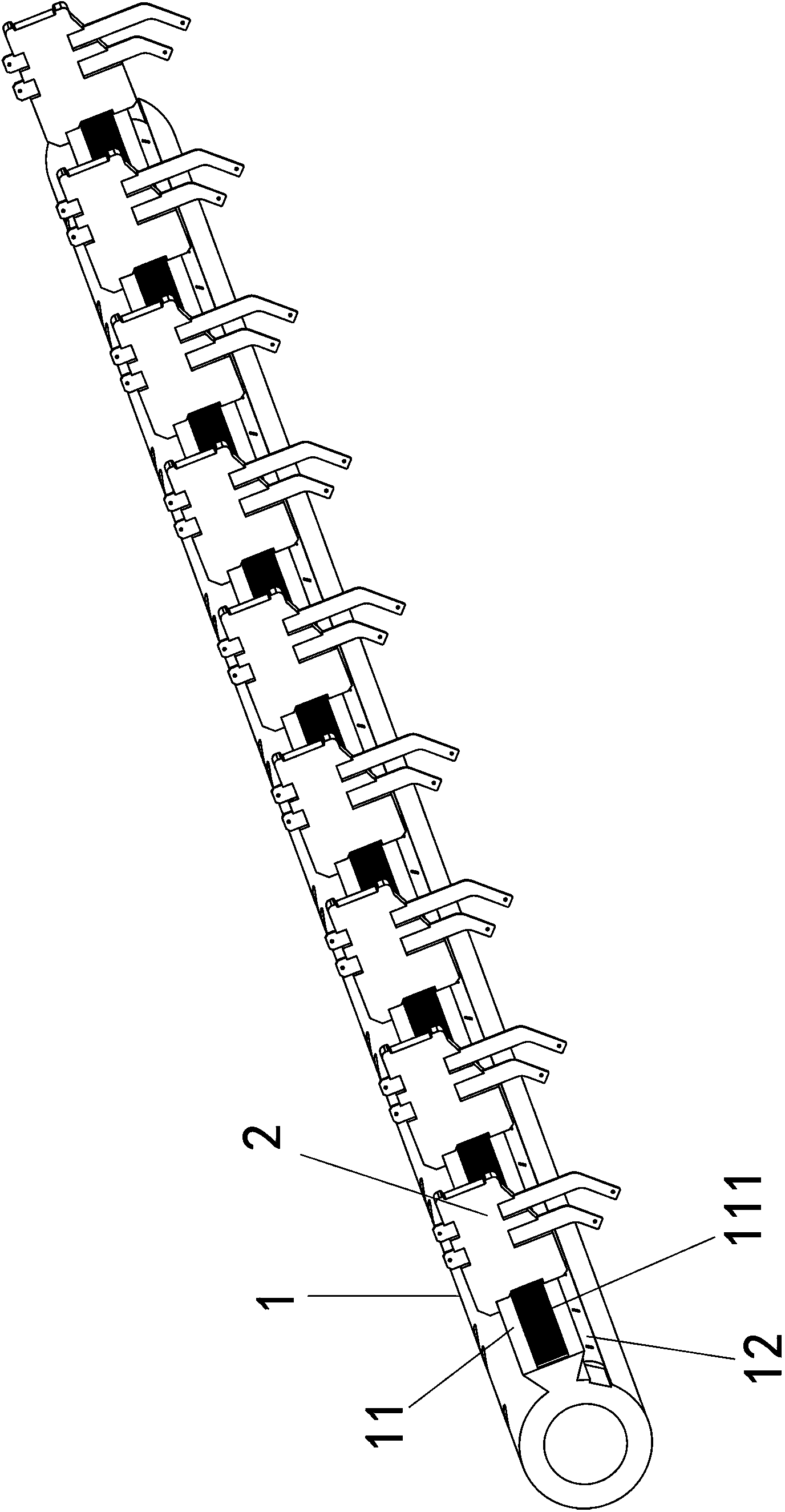
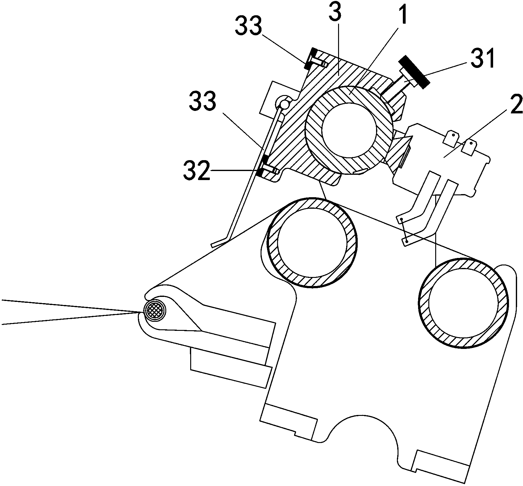
[0027] Example: such as Figure 1-3 As shown, a trademark cutting mechanism includes a knife rest 1, and a slide rail 11 extending along the length direction of the knife rest 1 is provided on the knife rest 1; a plurality of side-by-side cutters 2 are slidably connected to the slide rail 11.

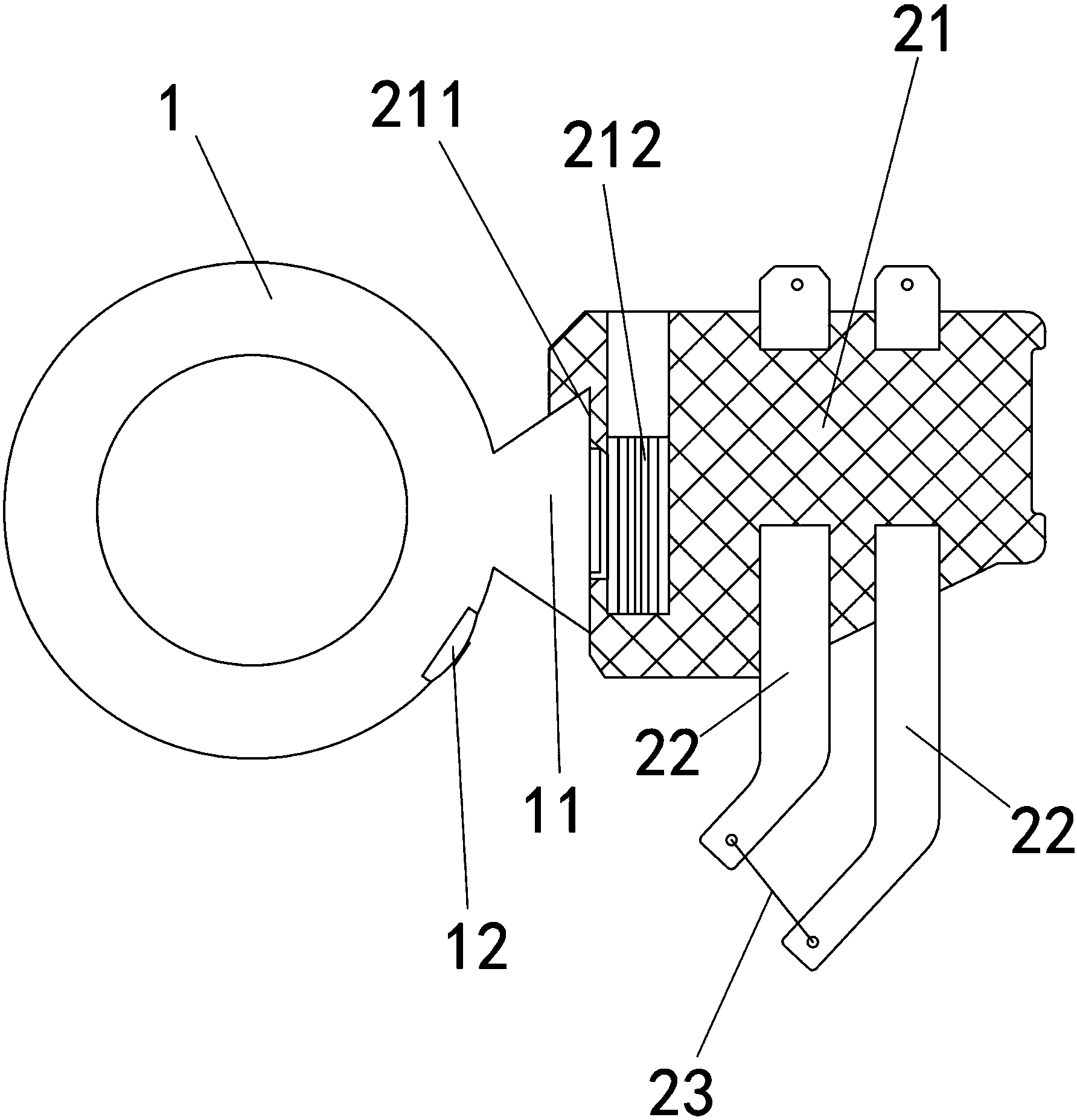
[0028] The cutter 2 includes a knife seat 21 on which two electrode sheets 22 are arranged, and a heating wire 23 for cutting trademarks is electrically connected between the lower ends of the two electrode sheets 22 .

[0029] The knife seat 21 is provided with a socket 211 which is slidably socketed on the slide rail 11; the cross section of the slide rail 11 is dovetail-shaped; the shape of the socket 211 matches the slide rail 11; A rack 111 is provided; the knife holder 21 is rotatably connected with an adjustment column 212 capable of engaging the rack 111; a notch should be provided on the upper end of the adjustment column 212 to facilitate the application of specific tools, suc...


PUM


Abstract

The invention relates to trademark processing, in particular to a trademark cutting mechanism. According to the technical scheme, the trademark cutting mechanism comprises a tool rest and cutters arranged side by side along the length direction of the tool rest, wherein each cutter comprises a tool apron arranged on the tool rest, two electrode plates arranged on the tool apron and a heating wire electrically connected between the two electrode plates and used for cutting trademarks. The trademark cutting mechanism is favorable for processing of the trademarks in batches.

Description

technical field [0001] The invention relates to trademark processing, in particular to a trademark cutting mechanism. Background technique [0002] The prior art, such as a trademark cutting machine disclosed in the utility model patent with the authorized announcement number CN202045684U, is mainly composed of a box body, a heating wire and a transformer. The upper surface of the box body is respectively vertically fixed with two hollow insulating columns. The two ends of the heating wire are respectively fixed on the hollow insulating column, and are connected with the secondary tap of the transformer through the wire, and the transformer is fixed inside the box; this kind of cutting machine is too simple and cannot be applied to the batch processing of trademarks. Contents of the invention [0003] The purpose of the present invention is to provide a trademark cutting mechanism, which is beneficial to realize batch processing of trademarks. [0004] The above-mentioned...

Claims


Application Information

Patent Timeline
Patent Type & Authority Applications(China)
IPC IPC(8): B26F3/12B26D7/26
Inventor 韦文泉孙立新费利章
Owner HUZHOU HYUNDAI TEXTILE MACHINERY
Why Eureka
Try Eureka