
Combined measuring method based on two-point center-alignment model

A measurement method and model technology, applied in the direction of measurement devices, surveying and navigation, compass, etc., to achieve the effect of simple and easy method

Active Publication Date: 2015-02-04
THE PLA INFORMATION ENG UNIV
View PDF5 Cites 5 Cited by
  • Summary
  • Abstract
  • Description
  • Claims
  • Application Information

AI Technical Summary

Benefits of technology

This technology allows for accurate measurements on both directions by measuring their positions with an optically controlled device called a goniometer or scanner. It then calculates its coordinates based upon these data from this reference frame (the ground). By comparing them against each other's own coordinate systems, it can determine if they were located at right angles towards one another. These calculations help improve navigation accuracy during flight operations.

Problems solved by technology

This patented technology allows accurate determination of an object's position when there may have unknown or unpredictable directions from its original location (true North). However, these existing techniques require many repetitions before they become reliable over longer periods due to their limitations such as requiring precise knowledge about how the device was used during flight.

Method used


Image

  • Combined measuring method based on two-point center-alignment model
  • Combined measuring method based on two-point center-alignment model
  • Combined measuring method based on two-point center-alignment model

Examples


Embodiment Construction

[0025] The specific embodiments of the present invention will be further described below in conjunction with the accompanying drawings.

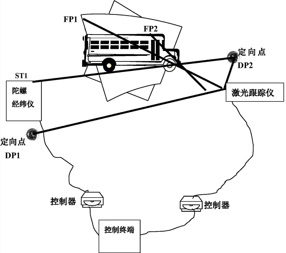
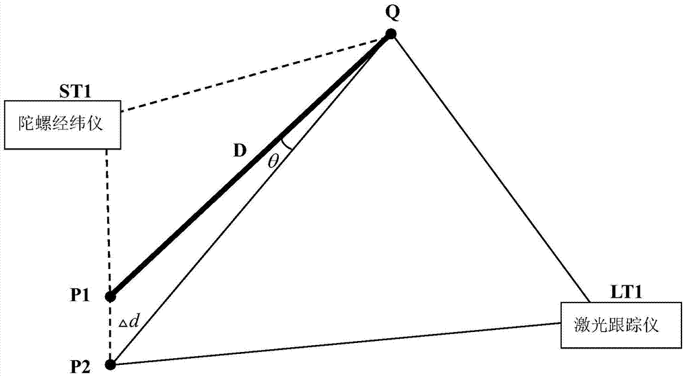
[0026] Take the main process of calculating the true north position of the target point of the launch vehicle as an example below to illustrate the specific implementation process of the present invention, as figure 1 As shown, firstly, the true north azimuth α of the spatial orientation point is accurately measured by using the gyro theodolite i ; Then the laser tracker is accurately leveled, and the coordinate value (x i the y i z i ), and calculate the azimuth angle value β of the orientation point in the laser tracker coordinate system i ;According to the different orientation values ​​corresponding to the orientation point (α i beta i ), the conversion parameters between the gyro theodolite coordinate system and the laser tracker coordinate system (0,0,0,0,0, ), the most important parameter here is the rotation angle of the tw...


PUM


Abstract

The invention relates to a combined measuring method based on a two-point center-alignment model and belongs to the technical field of engineering measurement. In the method, firstly a gyro theodolite is employed for accurately measuring a true north orientation [alpha]i of a connecting line between two orientation points in space, and then a laser tracker is employed for measuring coordinate values of the two orientation points in a leveling coordinate system and an orientation angle value [beta]1 of the connecting line between the two orientation points in the coordinate system, and then a conversion parameter (0,0,0,0,0,[partial]), and finally the laser tracker is employed for measuring the coordinate value of a target point of an launching vehicle so that the orientation of the connecting line of the target point in the coordinate system of an instrument is back-calculated and the true north orientation of the connecting line of the target point is calculated according to the conversion parameter. By means of the two-point center alignment coordinate system transfer model, coordinate systems of the laser tracker and the gyro theodolite are integrated so that the true north orientation of the model launching vehicle is directly measured and obtained under the coordinate system of the laser tracker. The method is simple and easy to carry out.

Description


Claims


Application Information

Patent Timeline
Owner THE PLA INFORMATION ENG UNIV
Learn More