Current-limiting small-sized breaker
A technology of small circuit breakers and current limiting coils, applied in circuit breaker parts and other directions, can solve problems such as poor breaking capacity and current limiting performance, and achieve the effect of improving breaking capacity, high arc voltage, and high current limiting performance
- Summary
- Abstract
- Description
- Claims
- Application Information
AI Technical Summary
Problems solved by technology
Method used
Image

Examples
Embodiment 1
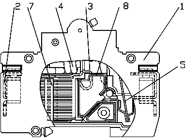
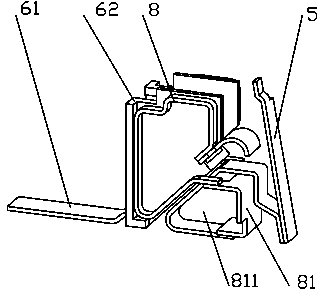
[0037] Embodiment one: refer to attached Figure 1-6 , when a short-circuit current occurs on the load side, the miniature circuit breaker operates, and the moving contact and the static contact separate to generate an arc 9; at this time, the circuit current passes through the tripping system 4 from the incoming terminal 21 (the tripping system of the miniature circuit breaker includes Excitation release), static contact 32, arc 9, moving contact 31, internal conductor of circuit breaker, bimetal sheet 5 (referring to the tripping piece formed by two different metal parts), wire, and outlet terminal 22 flows to the load; the arc 9 generates steam under the action of magnetic blowing and the contact between the arc 9 and the insulator 62, forming a pressure difference before and after the arc 9, so that the arc 9 moves quickly to the arc striker 61, when the arc root at one end of the arc moves to the arc striker 61 , The circuit current flows from the incoming terminal 21 thr...
Embodiment 2
[0038] Embodiment two: refer to attached Figure 7 with 8 , the current direction of the second embodiment is opposite to that of the first embodiment.
Embodiment 3
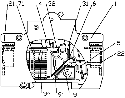
[0039] Embodiment three: refer to attached Figure 9-13 , Embodiment 3 has the same current direction as Embodiment 1, but the shapes of the current-limiting coil and the arc striker are different.
[0040] Specifically, the current-limiting coils and arc-leading pieces in the examples of all embodiments can be in any shape, and the material can be any conductive material. The current-limiting coil is preferably provided with a certain resistance, which can better limit flow effect. The bimetal sheet and the terminal are connected by wires, the wires can be in any shape, and the material can be any conductive material, such as plate, strip, profile, hard material or soft material.
PUM
 Abstract
Description
Claims
Application Information
 - Generate Ideas
- Intellectual Property
- Life Sciences
- Materials
- Tech Scout
- Unparalleled Data Quality
- Higher Quality Content
- 60% Fewer Hallucinations
Browse by: Latest US Patents, China's latest patents, Technical Efficacy Thesaurus, Application Domain, Technology Topic, Popular Technical Reports.
© 2025 PatSnap. All rights reserved.Legal|Privacy policy|Modern Slavery Act Transparency Statement|Sitemap|About US| Contact US: help@patsnap.com