Double-frequency wearable fabric antenna

A fabric and antenna technology, applied in antennas, slot antennas, antenna supports/mounting devices, etc., can solve the problems of antennas being difficult to wear and easy to be discovered by the outside world

Inactive Publication Date: 2015-02-04
NO 54 INST OF CHINA ELECTRONICS SCI & TECH GRP
View PDF1 Cites 0 Cited by
  • Summary
  • Abstract
  • Description
  • Claims
  • Application Information

AI Technical Summary

Problems solved by technology

[0003] The technical problem to be solved by the present invention is to provide a dual-frequency wearable fabric antenna. The purpose of the present invention is to solve th

Method used


Image

  • Double-frequency wearable fabric antenna

Examples


Embodiment Construction

[0017] The present invention will be further described in detail below in conjunction with the accompanying drawings and specific embodiments.

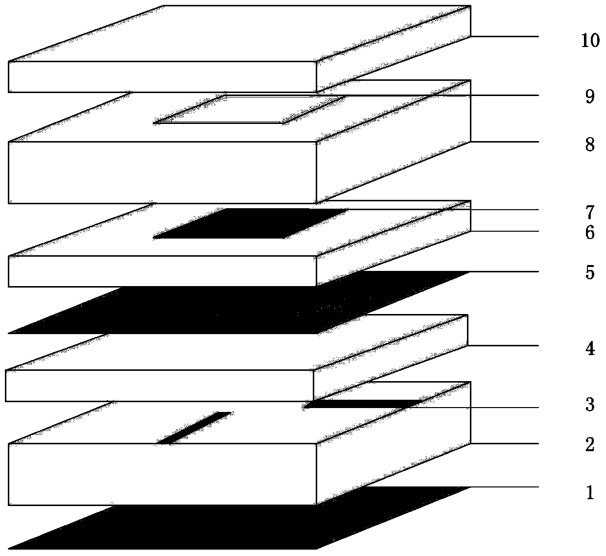
[0018] Such as figure 1 As shown, a dual-frequency wearable fabric antenna according to the present invention includes a reflector layer 1, a first support layer 2, a feed layer 3, a first fabric layer 4, a coupling slot layer 5, and a second fabric layer 6 , radiation patch layer 7, second support layer 8, parasitic patch layer 9 and third fabric layer 10, reflector layer 1, first support layer 2, feed layer 3, first fabric layer 4, coupling gap layer 5. The second fabric layer 6, the radiation patch layer 7, the second supporting layer 8, the parasitic patch layer 9 and the third fabric layer 10 are sequentially stacked.

[0019] The feed layer 3 is composed of two mutually perpendicular and non-intersecting strip-shaped patches. One end of each of the two strip-shaped patches is respectively flush with and perpendicular to the two...


PUM


Abstract

The invention discloses double-frequency wearable fabric antenna. The double-frequency wearable fabric antenna is composed of a reflection plate layer (1), a first support layer (2), a feed layer (3), a first fabric layer (4), a coupling gap layer (5), a second fabric layer (6), a radiation patch layer (7), a second support layer (8), a parasitic patch layer (9) and a third fabric layer (10) in a successive stacking mode. The double-frequency wearable fabric antenna is light and soft, capable of really achieving antenna wearing, and difficult to be discovered by the outside world in the battlefield environment. The double-frequency wearable fabric antenna supports double-frequency work and can well work at ISM frequency band.

Description

technical field [0001] The invention relates to the field of a microstrip antenna supporting dual-frequency operation for wireless communication, in particular to a wearable fabric antenna. Background technique [0002] In army operations, the traditionally used antenna is the whip antenna, the target is obvious, and it is easy to become the target of the opponent's snipers. Existing traditional antennas are made of metal and cannot be easily hidden in clothing. Contents of the invention [0003] The technical problem to be solved by the present invention is to provide a dual-frequency wearable fabric antenna. The purpose of the present invention is to solve the problems that traditional antennas are difficult to wear and easy to be discovered by the outside world, and provide support for home networking and battlefield environments. [0004] In order to solve the problems of the technologies described above, the technical solution adopted in the present invention is: ...

Claims


Application Information

Patent Timeline
IPC IPC(8): H01Q1/38H01Q13/10H01Q5/10H01Q15/14H01Q1/22
Inventor 刘宁汪春霆杜彪袁宏伟宋跃
Owner NO 54 INST OF CHINA ELECTRONICS SCI & TECH GRP
Why Eureka
Try Eureka