Bidirectional floating adapter and adapting contact assembly thereof

A technology of floating contacts and contacts, which is applied to the parts, connections, electrical components, etc. of the connection device, which can solve the problem of limited precision and difficulty in mating the adapter and the corresponding connector, and the adapter and the corresponding connector For problems such as plugging failure, to achieve a good contact effect

Inactive Publication Date: 2015-02-04
CHINA AVIATION OPTICAL-ELECTRICAL TECH CO LTD
View PDF6 Cites 6 Cited by
  • Summary
  • Abstract
  • Description
  • Claims
  • Application Information

AI Technical Summary

Problems solved by technology

In the first case, since the adapter itself is not fixed, it is easy to achieve mating with the two plugs; however, in the second case, since the adapter is often fixedly assembled on the corresponding It is installed on the panel, and the connectors to be mated with it are often assembled on some chassis with prescribed moving routes, which makes it difficult to realize the mating between the adapter and the corresponding connector. The reason is that The main reason is that the walking path of the connector box often has limited accuracy, and it is easy to have problems such as mutual deflection between the adapter and the connector. In addition, in view of the manufacturing and assembly accuracy of the connector's contact parts, it may exist in length. Deviation, it is possible that the connector and the chassis where it is located are not fully inserted in place, any of the above situations will lead to the failure of the adapter and the corresponding connector to be mated
[0003] In order to solve the above problems, floating adapters began to appear on the market, but most of the currently visible floating adapters float as a whole and can only float along the direction of insertion, which obviously cannot solve the above problems

Method used


Image

  • Bidirectional floating adapter and adapting contact assembly thereof
  • Bidirectional floating adapter and adapting contact assembly thereof

Examples


Embodiment Construction

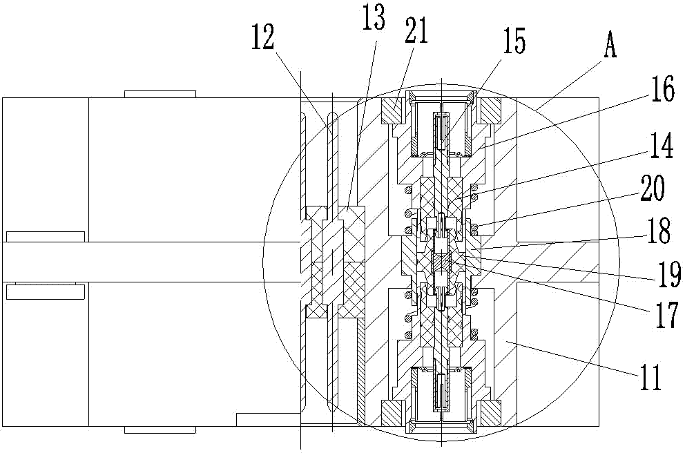
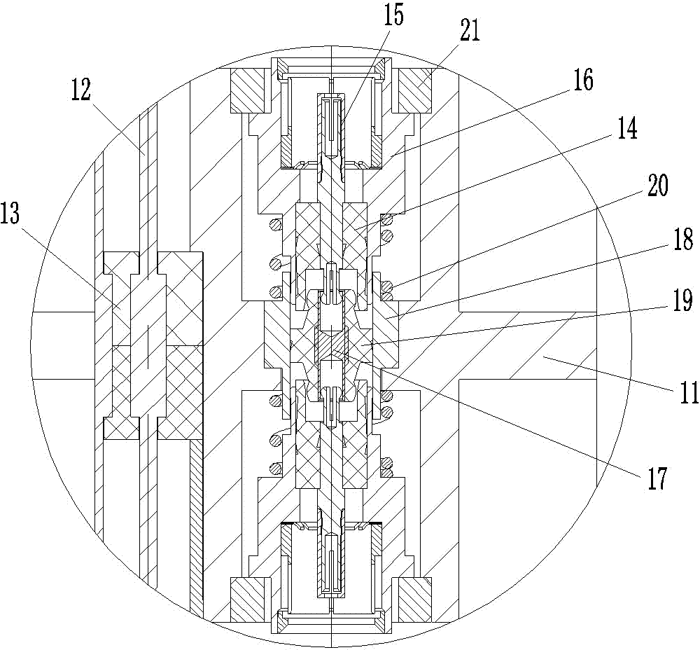
[0020] Examples of bidirectional floating adapters, such as Figure 1-2 , a two-way floating adapter, including a housing 11 and a transfer contact assembly.

[0021] Housing 11 is provided with mounting holes. In this embodiment, the two-way floating adapter is a high-low frequency mixed adapter, so the mounting holes on the housing are divided into high-frequency transfer contact mounting holes and low-frequency contact mounting holes.

[0022] As mentioned above, the two-way floating adapter is a high-low frequency mixed adapter, wherein the low-frequency transfer contact 12 is a pin contact, which is fixedly assembled in the low-frequency installation hole through the low-frequency insulator 13, and the low-frequency transfer contact The structure and assembly method of the component 12 are prior art, and will not be repeated here.

[0023] The transfer contact assembly mentioned above is equivalent to a high-frequency contact. In this embodiment, the transfer contact as...


PUM


Abstract

The invention relates to the field of electrical connectors and particularly relates to a bidirectional floating adapter and an adapting contact assembly thereof. The bidirectional floating adapter includes a casing. Installation holes are arranged in the casing. The adapting contact assembly is assembled in the installation holes. The adapting contact assembly includes floating contacts and a fixed contact part. Resetting springs are installed between the floating contacts and the fixed contact in a butting manner. Swing gaps are arranged between the floating contacts and the walls of the installation holes. Each floating contact includes a floating conductor and the fixed contact includes a fixed conductor. The floating conductors and the fixed conductor are in plug-in connection through plug-in heads and plug-in holes arranged in the floating conductors and the fixed conductor respectively. The plug-in heads and the plug-in holes cooperate so that a universal swing structure is formed. The adapter is a bidirectional floating adapter, the contact parts of which are capable of floating and swinging in the axial and radial directions.

Description

technical field [0001] The invention relates to the field of electrical connectors, in particular to a bidirectional floating adapter and an adapter contact assembly thereof. Background technique [0002] The adapter is a common part of the interconnection between two connectors. In the process of actual use, there are mainly two occasions for the use of the adapter, one is for the direct connection between two plugs that can move freely, and its function is equivalent to a terminal; the other is for the chassis or equipment shell Intercommunication of connectors on both sides inside and outside the body. In the first case, since the adapter itself is not fixed, it is easy to achieve mating with the two plugs; however, in the second case, since the adapter is often fixedly assembled on the corresponding It is installed on the panel, and the connectors to be mated with it are often assembled on some chassis with prescribed moving routes, which makes it difficult to realize...

Claims


Application Information

Patent Timeline
Patent Type & Authority Applications(China)
IPC IPC(8): H01R12/91H01R31/06
CPCH01R13/6315H01R31/06
Inventor 王小林薛江付志方
Owner CHINA AVIATION OPTICAL-ELECTRICAL TECH CO LTD
Why Eureka
Try Eureka