Ger lever for operation device of automobile gear-box

A technology for automobile gearboxes and shift levers, which is applied in the field of shift levers, and can solve problems such as laborious work of the shift levers and shift shafts

Inactive Publication Date: 2009-05-06
SCHAEFFLER TECH AG & CO KG
View PDF5 Cites 4 Cited by
  • Summary
  • Abstract
  • Description
  • Claims
  • Application Information

AI Technical Summary

Problems solved by technology

[0005] In particular, the coupling of the gear lever to the selector shaft is relatively labor-intensive, since the pivoting movement has to be converted into a linear adjustment movement

Method used


Image

  • Ger lever for operation device of automobile gear-box
  • Ger lever for operation device of automobile gear-box
  • Ger lever for operation device of automobile gear-box

Examples


Embodiment Construction

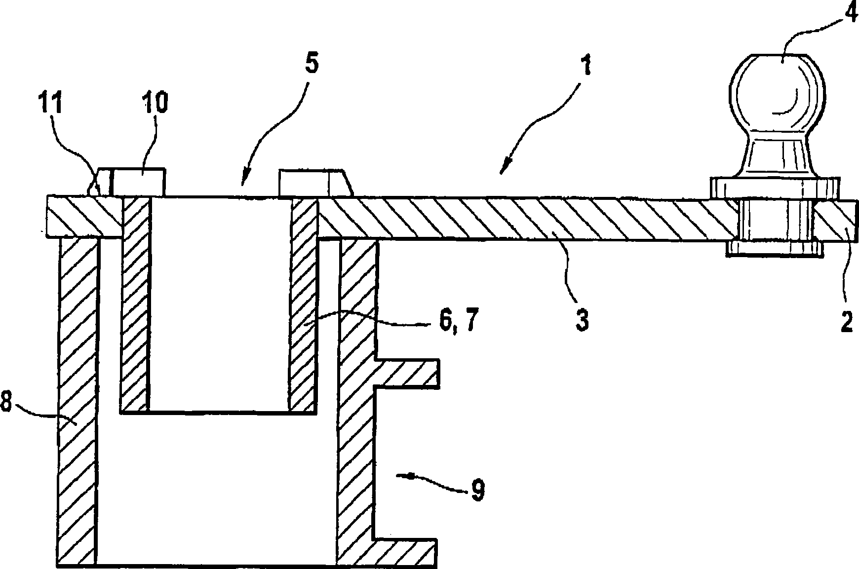
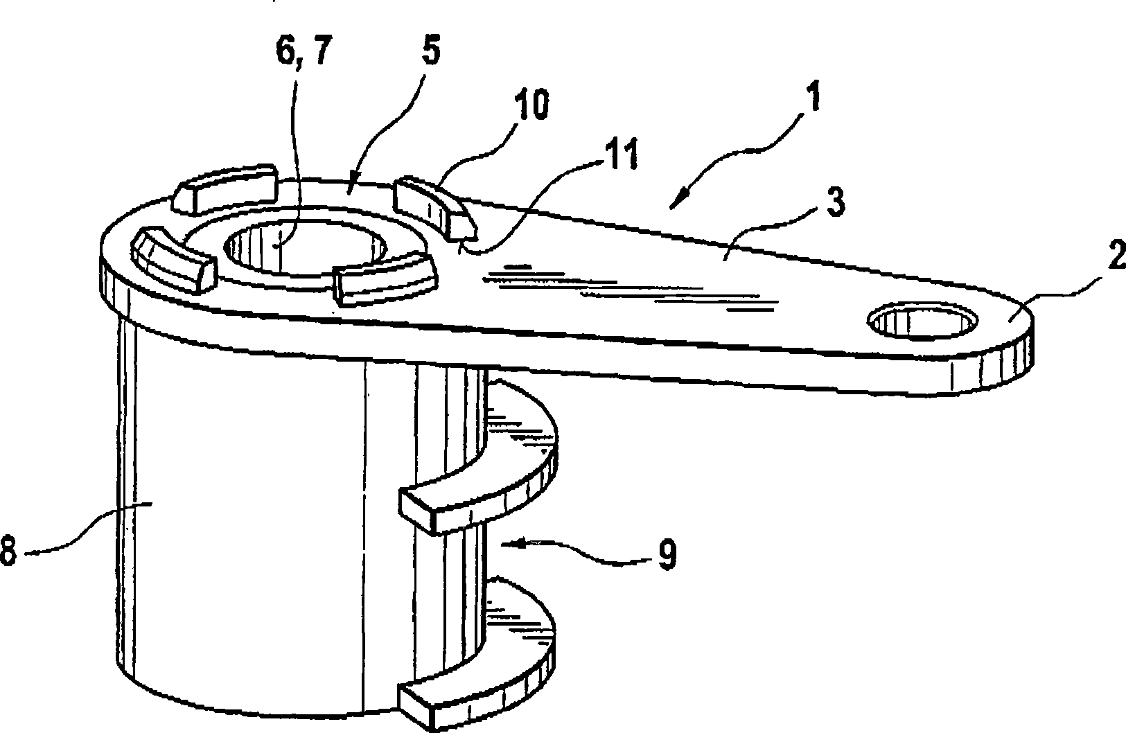
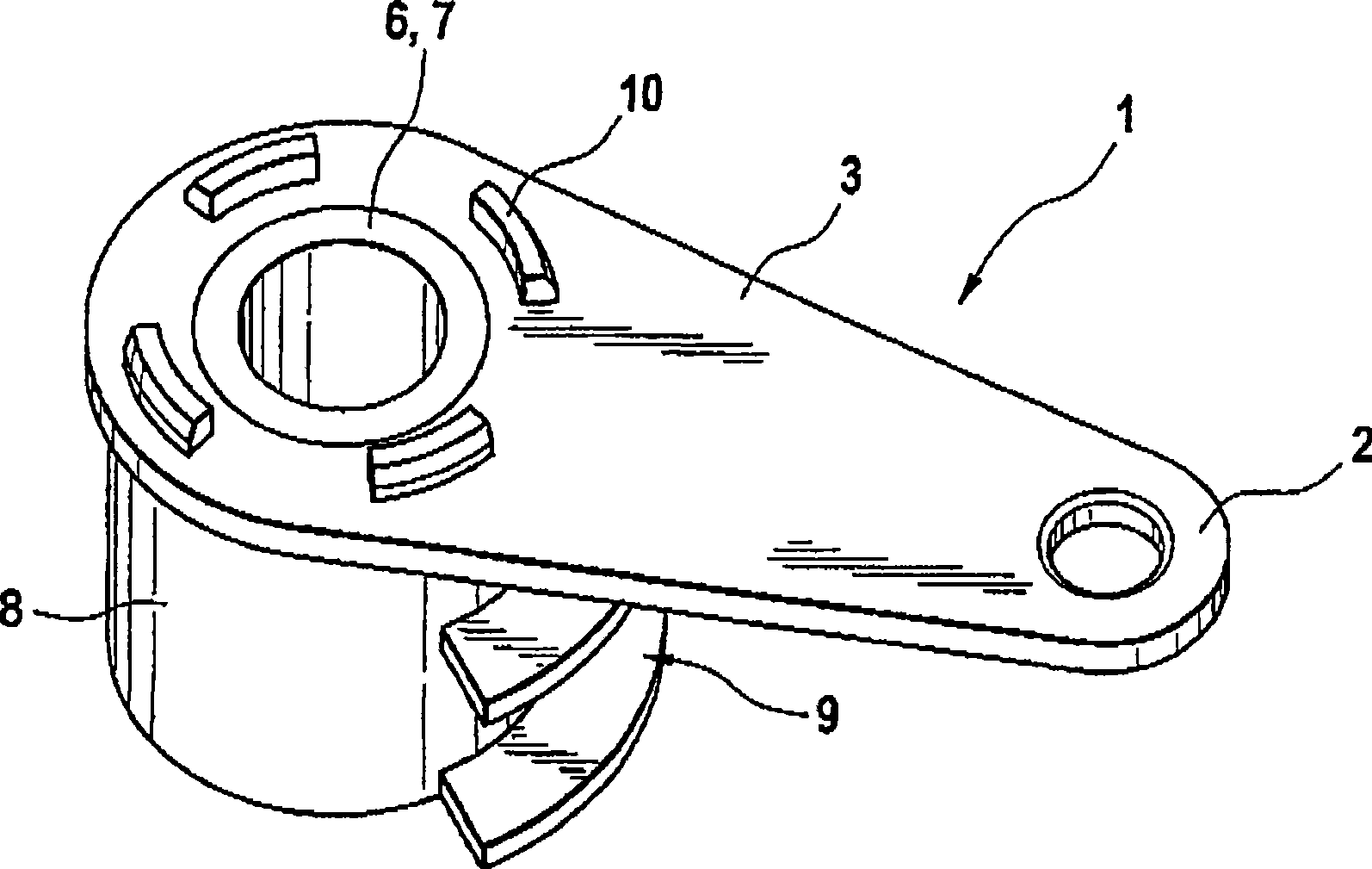
[0021] Figures 1 to 4 The schematic diagram of FIG. 1 illustrates the structure and operating principle of a first variant of the gear lever 1 , which is a component part of an operating device for a gearbox (not shown) of a motor vehicle. The selector lever 1 generally remains operatively connected to a gearshift shaft (not shown) of the gearbox and is used for axial displacement of this gearshift shaft. The shift shaft is mounted rotatably and axially displaceably in the gearbox housing. A selector lever (not shown) is usually fixed in a rotationally fixed manner on the end face of the selector shaft, so that the selector shaft can be rotated by a pivotal movement of the selector lever by a defined rotational angle amount, which is necessary for switching the shift stages is compulsory. The selector shaft can be displaced in the axial direction by means of the illustrated selector lever 1 . In the illustrated embodiment, the selector lever 1 is provided with a ball head ...


PUM


Abstract

The present invention relates to a gear lever (1) which is used for transforming the pivoting movement of lever to the axial process of gearshift shaft of vehicle gearbox. The gear lever (1) comprises a sliding sleeve (6) which keeps effective connection with the gearshift shaft. The sliding sleeve (6) and a hub part (5) of the gear lever (1) which can pivot are connected through a mode with rotation resistance.

Description

technical field [0001] The invention relates to a selector lever for an operating device of a motor vehicle gearbox, the selector lever having the features of the preamble of claim 1 . Background technique [0002] In motor vehicles with manual or automatic transmissions, an actuating device is required for shifting or rotating the selector shaft, which usually consists of two levers. The first lever of the arrangement is pivoted in order to axially displace the shift shaft. Here, the shifting movement at the selector lever is converted into a linear movement of the selector shaft. Another lever rotates the shift shaft for eg shifting and inserting gears. These two rods are kinematically connected with a manual shift lever or a servo motor through a connecting rod, a pulley block, etc. [0003] Such operating devices are known, for example, from DE 197 54 760 A1, DE 101 11 911 A1, DE 10138 729 A1 and EP 0 933 563 A1. [0004] Furthermore, DE 195 46 547 C1 discloses a shi...

Claims


Application Information

Patent Timeline
Patent Type & Authority Applications(China)
IPC IPC(8): F16H59/04F16H61/24B60K20/02
CPCF16H61/26F16H2063/3076
Inventor 瓦尔德马·迈尔伊万·斯坦丘
Owner SCHAEFFLER TECH AG & CO KG
Why Eureka
Try Eureka