
Ultrasound transducer arrays with variable patch geometries

A technology of transducers and facets, applied in the field of diagnostic systems, can solve the problems of expensive, multi-parallel processor microbeam formers and other complex problems, and achieve no discontinuous effect

Active Publication Date: 2015-02-04
KONINKLJIJKE PHILIPS NV
View PDF11 Cites 0 Cited by
  • Summary
  • Abstract
  • Description
  • Claims
  • Application Information

AI Technical Summary

Problems solved by technology

A microbeamformer with multiple parallel processors for each transducer element of a 2D array would be extremely complex, expensive, and constrained by the space available in a handheld transducer probe

Method used


Image

  • Ultrasound transducer arrays with variable patch geometries
  • Ultrasound transducer arrays with variable patch geometries
  • Ultrasound transducer arrays with variable patch geometries

Examples


Embodiment Construction

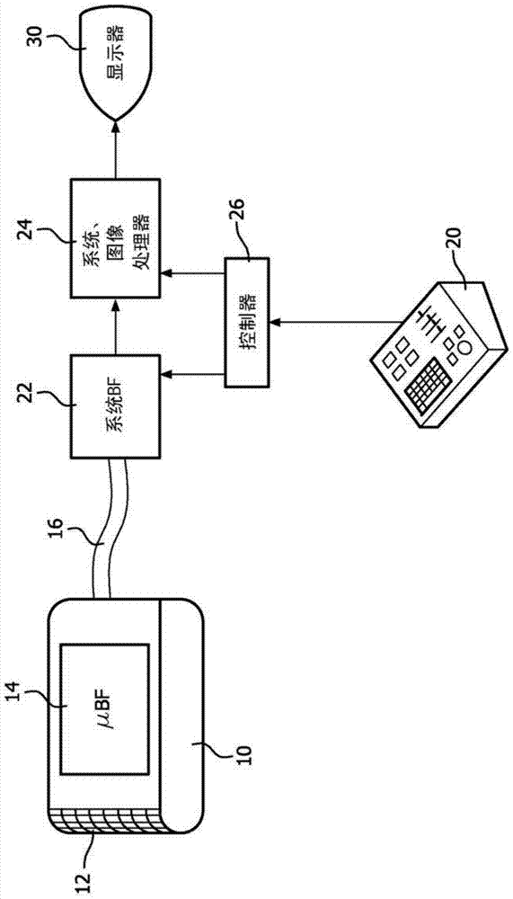
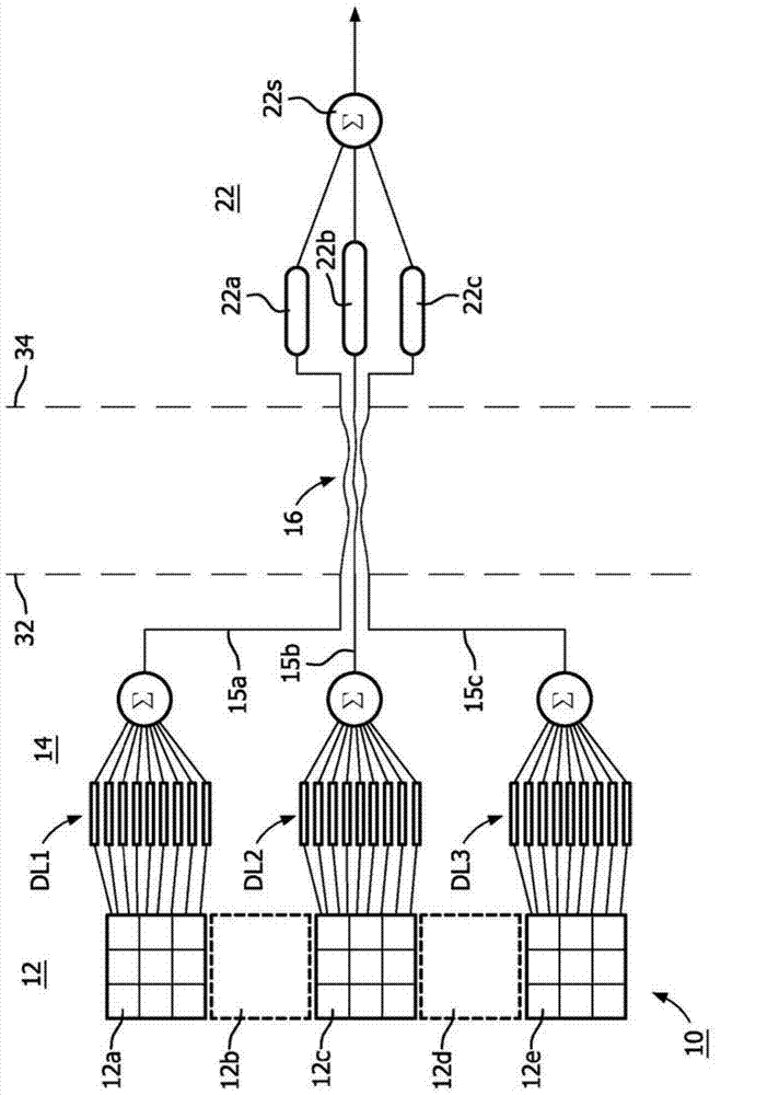
[0016] first reference figure 1 , shows in block diagram form an ultrasound system constructed in accordance with the principles of the present invention. The probe 10 has a two-dimensional array transducer 12 that is curved in the altitude dimension, such as shown in US Patent 7927280 (Davidsen). The elements of the array are coupled to a microbeamformer 14 located in the probe behind the transducer array. The microbeamformer applies timed transmit pulses to elements of the array to transmit beams in desired directions and to desired focal points in a three-dimensional image field in front of the array. Echoes from the transmitted beams are received by the array elements and coupled to the channels of the microbeamformer 14 where they are individually delayed. The delayed signals from the transducer elements of a patch are combined to form a partial sum signal for the patch. As used herein, the term "patch" refers to a group of transducer elements that are contiguous or op...


PUM


Abstract

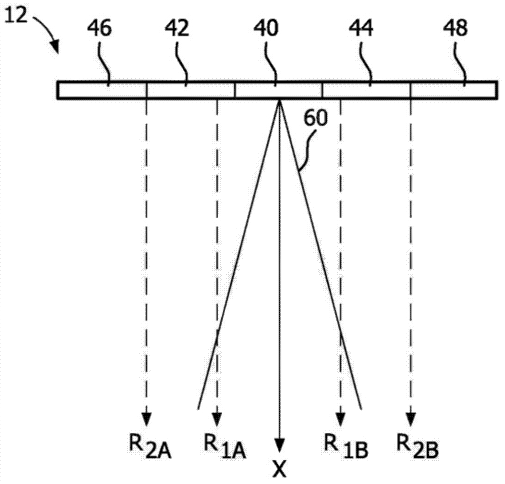
A two dimensional ultrasonic array transducer receives echo signals from increasing depths of a volumetric region. The 2D array is configured into patches of elements which are processed by a microbeamformer and summed signals from a patch are coupled to a channel of an ultrasound beamformer At the shallowest depth the 2D array receives echoes from small patches in the center of the aperture. As signals are received from increasing depths the aperture is grown by symmetrically adding patches of progressively larger sizes on either side of the small patches in the center. The inventive technique can improve the multiline performance of both ID and 2D array probes.

Description

technical field [0001] The present invention relates to medical diagnostic ultrasound systems, and more particularly to diagnostic systems having an array transducer having elements grouped into patches and operating with a microbeamformer. Background technique [0002] Ultrasound array transducers, transducers having a plurality of individually controllable transducer elements, have been developed in a variety of configurations. Annular arrays consist of an annular ring of elements and are ideal for delivering a tightly focused beam all the way forward—that is, perpendicular to the plane of the transducer elements. The elements of a 1D array consist of a single row of elements (or multiple rows connected to operate in unison) that can scan a single image plane, the azimuthal plane, perpendicular to the row of elements. A 1.5D array consists of rows of elements that can be operated symmetrically in altitude to scan the azimuth plane perpendicular to the array, but with beam...

Claims


Application Information

Patent Timeline
Patent Type & Authority Applications(China)
IPC IPC(8): G01S15/89
CPCA61B8/4488G01S7/5208G01S15/8925G01S15/8927G01S15/8993G01S7/52095G10K11/346G01S15/89
Inventor B·J·萨沃德
Owner KONINKLJIJKE PHILIPS NV
Learn More