Gas distributor for slurry bed reactor

A gas distributor and reactor technology, applied in chemical instruments and methods, chemical/physical processes, etc., can solve the problems of many vortices, frequent beating of check balls, complicated flow channels, etc., and achieve the effect of preventing backflow

Active Publication Date: 2015-02-11
LUOYANG PETROCHEMICAL ENG CORP SINOPEC +1
View PDF6 Cites 4 Cited by
  • Summary
  • Abstract
  • Description
  • Claims
  • Application Information

AI Technical Summary

Problems solved by technology

[0004] In order to solve the technical problems that the existing bubble cap distributor is used for distributing the gas feed in the slurry bed reactor, the non-return bal

Method used


Image

  • Gas distributor for slurry bed reactor
  • Gas distributor for slurry bed reactor
  • Gas distributor for slurry bed reactor

Examples


Embodiment Construction

[0017] The present invention will be further described below in conjunction with the accompanying drawings.

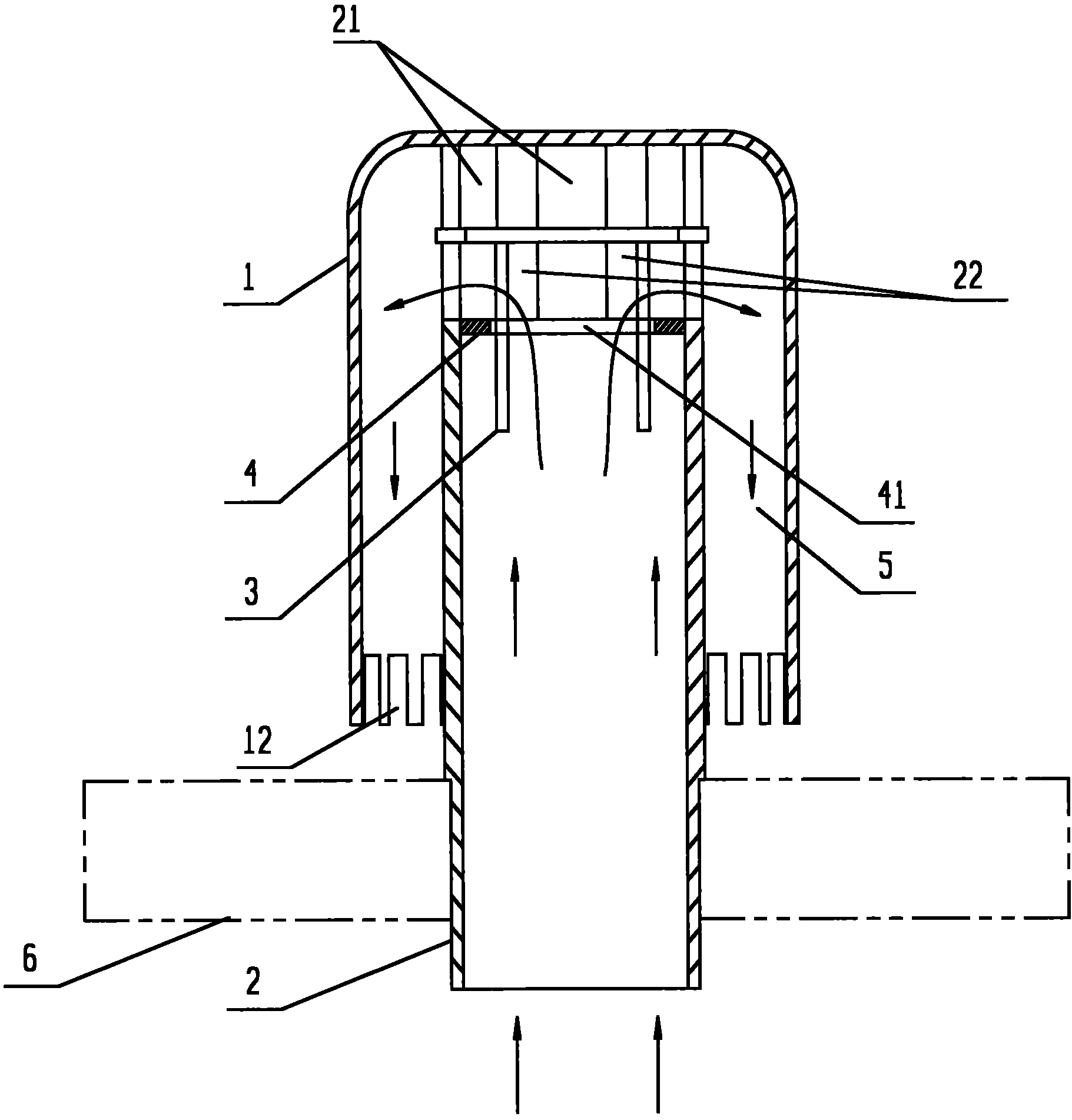
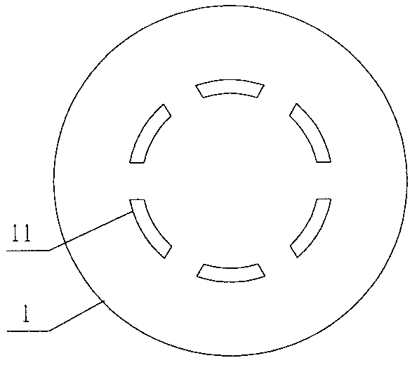
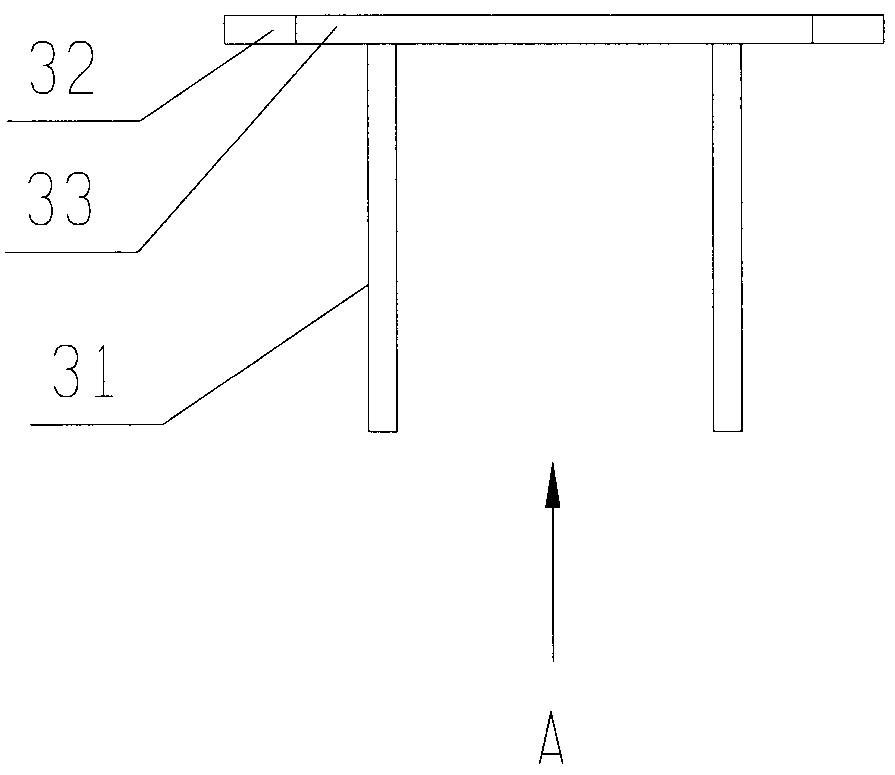
[0018] Such as figure 1 As shown, the gas distributor for a slurry bed reactor provided by the present invention is mainly composed of a central tube 2, a bubble cap 1, a float valve 3 and a valve seat 4; the bubble cap 1 is a cup-shaped cylinder, and the bubble cap 1 The bottom (that is, the blind end of the bubble cap) is a circular plane, and the connection between the bottom of the bubble cap and the tube wall is a round transition. Slit 12, the bubble cap 1 is covered on the upper end of the central tube 2, an annular channel 5 is formed between the inner cylinder wall of the bubble cap 1 and the outer wall of the central tube 2, and a bubble cap hole 11 is provided at the bottom of the bubble cap 1 (such as figure 2 shown); the central tube 2 passes through the installation hole on the distribution plate 6 and is fixed on the distribution plate 6, the gas outle...


PUM


Abstract

The invention discloses a gas distributor for a slurry bed reactor. The gas distributor for the slurry bed reactor mainly comprises a central pipe, a bubble cap, a floating valve and a valve seat, wherein the pipe wall of the upper end of the central pipe is provided with a gas outlet; a pipe opening in the lower end of the central pipe serves as a gas inlet; the bubble cap is a cover-shaped object with one opened end, and covers the upper end of the central pipe; a blind end of the bubble cap is fixedly connected with the upper end of the central pipe; the valve seat is of circular ring structure with a valve seat holes in the center, and is arranged below the gas outlet and in the central pipe; the floating valve is of a round plate-shaped structure, covers the valve seat and can move vertically along the axial direction of the central pipe. According to the invention, the floating valve acts as a non-return element, and runs stably; the special connection mode between the bubble cap and the central pipe enables a runner to be simple and resistance to be relatively low, thereby greatly weakening a vortex caused by air flow.

Description

technical field [0001] The invention relates to a gas distributor for a slurry bed reactor. Background technique [0002] The gas-liquid-solid three-phase slurry bed reactor is widely used in the Fischer-Tropsch synthesis reaction process in the field of petrochemical industry. When the slurry bed reactor is in operation, the gas feed enters the reactor from the bottom of the reactor, and after being distributed by the gas distributor, it is blown into the slurry containing solid catalyst particles to participate in the reaction. Gas phase reaction products and unreacted gas feed are separated in the upper part of the reactor, and the liquid reaction products are further refined after being separated from the catalyst, and the heat of reaction is removed by heat exchange facilities. Among them, the gas distributor is an important part to ensure the uniform distribution of the gas feed in the slurry bed and to increase the gas holdup of the slurry, mainly including orifice d...

Claims


Application Information

Patent Timeline
IPC IPC(8): B01J8/22
CPCB01J8/22B01J2208/00548B01J2208/00938
Inventor 蔡连波陈强赵晓青盛维武
Owner LUOYANG PETROCHEMICAL ENG CORP SINOPEC
Why Eureka
Try Eureka