
Gear burnishing fixture used for sleeve gears of synchronizers

A technology of synchronizers and gear sleeves, which is applied to components with teeth, gear teeth manufacturing devices, gear teeth, etc., can solve the problems of low processing efficiency, inconvenient installation and disassembly, and only one gear sleeve can be processed at a time. High processing efficiency and easy installation

Inactive Publication Date: 2015-02-11
重庆市德顺汽车部件制造有限公司
View PDF0 Cites 1 Cited by
  • Summary
  • Abstract
  • Description
  • Claims
  • Application Information

AI Technical Summary

Problems solved by technology

[0003] Existing tooth extrusion fixtures for synchronizer gear sleeves usually only include a positioning plate with a stepped inner circle. The positioning plate is connected to the machine tool through multiple bolts. Place a gear sleeve on the step of the inner circle of the positioning plate, and press the upper surface of the gear sleeve with the gland on the machine tool. During the gear extrusion process, the gear sleeve is positioned with the friction generated between the inner circle of the positioning plate. The disc rotates together, and the extrusion wheel rotates in the same direction and meshes with the tooth sleeve to extrude the gear. The gear extrusion fixture with this structure has the following problems: 1. Only one gear sleeve can be processed at a time, and the processing efficiency is low; 2. The positioning disc passes through multiple bolts It is inconvenient to install and disassemble when it is connected with the machine tool and needs to be replaced or repaired.

Method used


Image

  • Gear burnishing fixture used for sleeve gears of synchronizers
  • Gear burnishing fixture used for sleeve gears of synchronizers

Examples


Embodiment Construction

[0011] Below in conjunction with accompanying drawing and specific embodiment the present invention will be described in further detail:

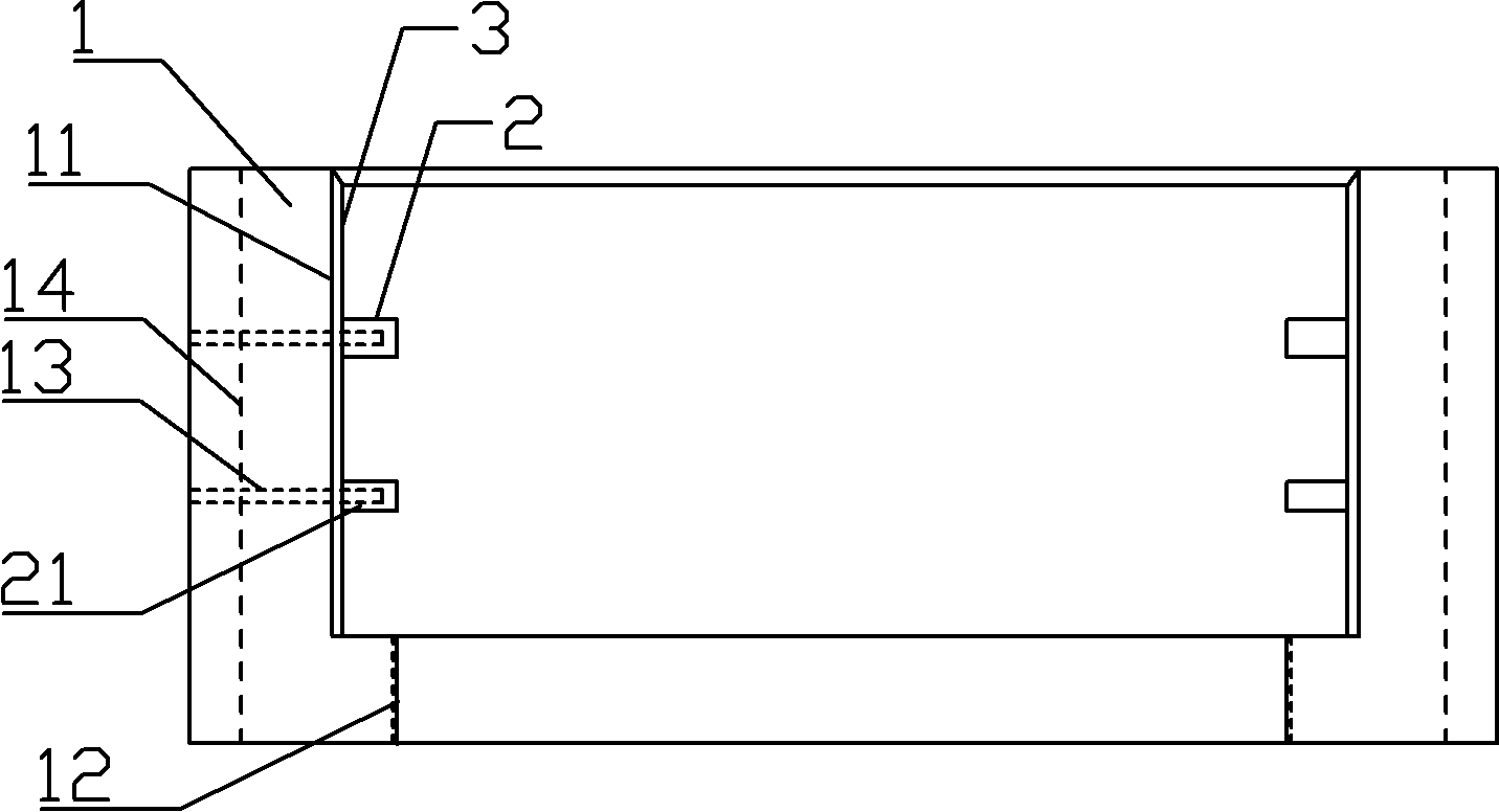
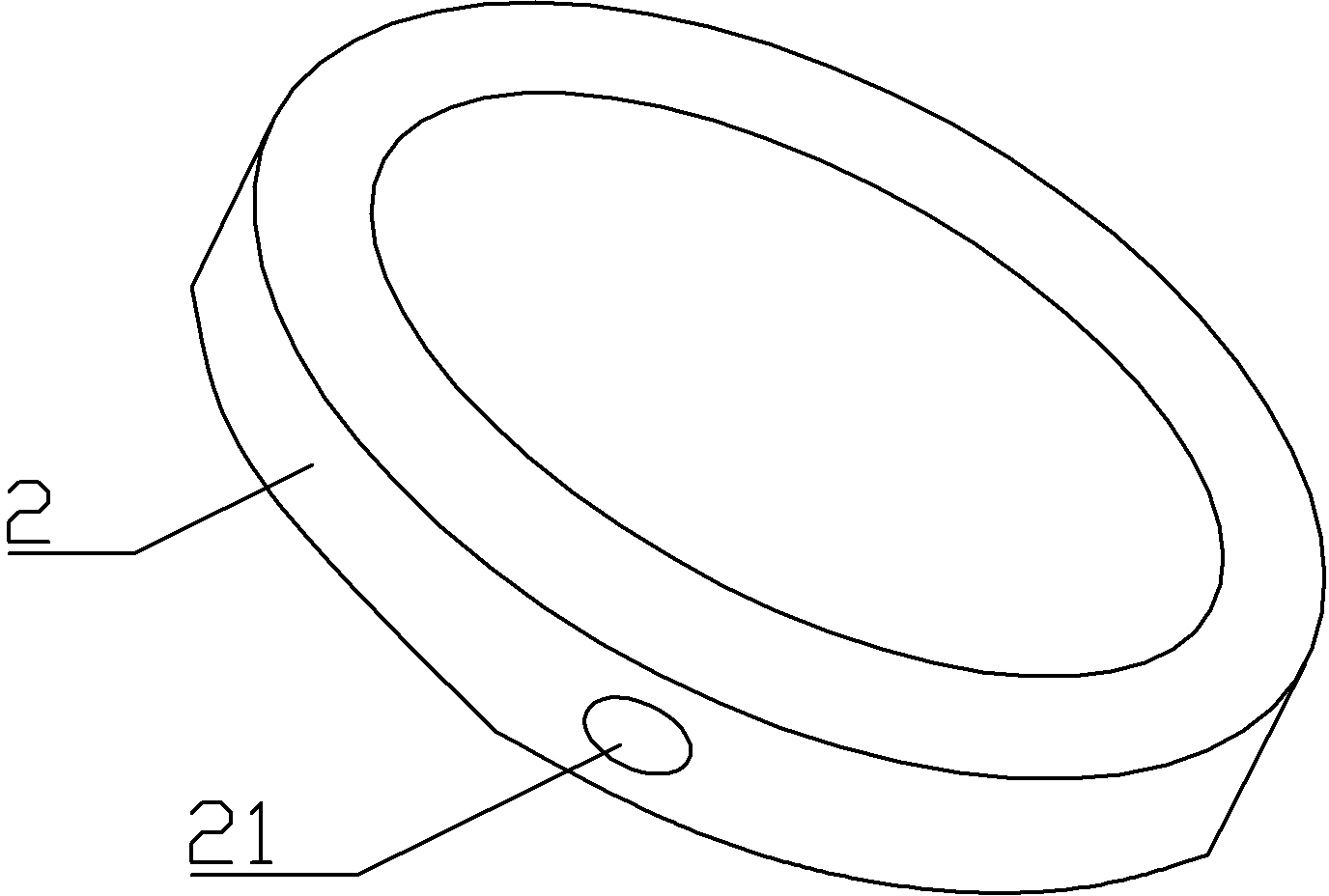
[0012] like figure 1 The tooth extrusion fixture for the synchronizer gear sleeve shown includes a positioning plate 1, an upper ring surface 11, a lower ring surface 12, a threaded hole 13, a groove 14, an annular pressure plate 2, a threaded column groove 21, and an annular friction plate 3.

[0013] The inner circle of the positioning disc 1 has an upper annular surface 11 and a lower annular surface 12, the inner circle of the lower annular surface 12 is provided with threads, the upper annular surface 11 and the lower annular surface 12 are stepped, and the upper annular surface 11 and the lower annular surface 12 The step between is the supporting portion for placing the tooth sleeve, and three threaded holes 13 are evenly distributed in the circumferential direction of the positioning plate 1, and two grooves 14 are evenly distribut...


PUM


Abstract

The invention provides a gear burnishing fixture capable of clamping a plurality of sleeve gears at a time, convenient to mount and used for sleeve gears of synchronizers. The invention provides a scheme as follows: the gear burnishing fixture used for the sleeve gears of synchronizers comprises a positioning disc; an inner circle of the positioning disc comprises an upper annular surface and a lower annular surface which are terraced, and further comprises a plurality of annular pressure discs arranged on an inner ring of the upper annular surface at equal intervals in the axial direction of the positioning disc; at least three thread column grooves are evenly distributed in the circumferential direction of each annular pressure disc; at least three thread holes corresponding to the thread column grooves in position are formed in the circumferential direction of the positioning disc; and threads are formed on an inner circle of the lower annular surface.

Description

technical field [0001] The invention relates to a jig, in particular to a gear extruding jig for a gear sleeve of a synchronizer. Background technique [0002] The synchronizer is an important part of the car. Its function is to synchronize the gears at the power output end with different speeds and the gears to be shifted into when shifting gears, so as to prevent the two gears with different speeds from directly meshing and causing damage to the teeth. Synchronizers generally include a spline hub, an adapter sleeve that engages with the outer spline of the spline hub, and two lock rings arranged on both sides of the spline hub. The adapter sleeve is the gear sleeve. After the gear sleeve is hobbed or shaped, It is also necessary to carry out finishing processing on the gear blank, that is, gear extrusion, which is processed by rolling and meshing the extrusion wheel and the gear sleeve in the same direction. The teeth of the synchronizer gear sleeve are inverted bevel t...

Claims


Application Information

Patent Timeline
Patent Type & Authority Applications(China)
IPC IPC(8): B23F23/06
Inventor 任德文
Owner 重庆市德顺汽车部件制造有限公司
Learn More