Liftable hinge device

A technology of hinges and hinges, which is applied in door/window accessories, buildings, wing leaf openers, etc., can solve the problems of short service life, high assembly cost, and unsightly appearance, and achieve long service life and beautiful appearance , low cost effect

Active Publication Date: 2015-02-11
吴裕龙 +2
View PDF11 Cites 6 Cited by
  • Summary
  • Abstract
  • Description
  • Claims
  • Application Information

AI Technical Summary

Problems solved by technology

This kind of self-closing device needs to be equipped with a shaft core and an elastic body, so it has the following disadvantages: a. Adding an elastic body is expensive; b. Inconvenient assembly and high assembly cost; c. Complex structure and high cost
The upper hinge is raised or the upper hinge is reset through the cooperation of the two helical edges, so there are the following disadvantages: a. It needs to be equipped with a shaft core, which is costly; b. The helical edge bears the gravity, and the helical edge bears the force transmission function, which is easy Damaged, short service life; c. Unattractive appearance; d. Only single helix can be set

Method used


Image

  • Liftable hinge device
  • Liftable hinge device
  • Liftable hinge device

Examples


Embodiment 1

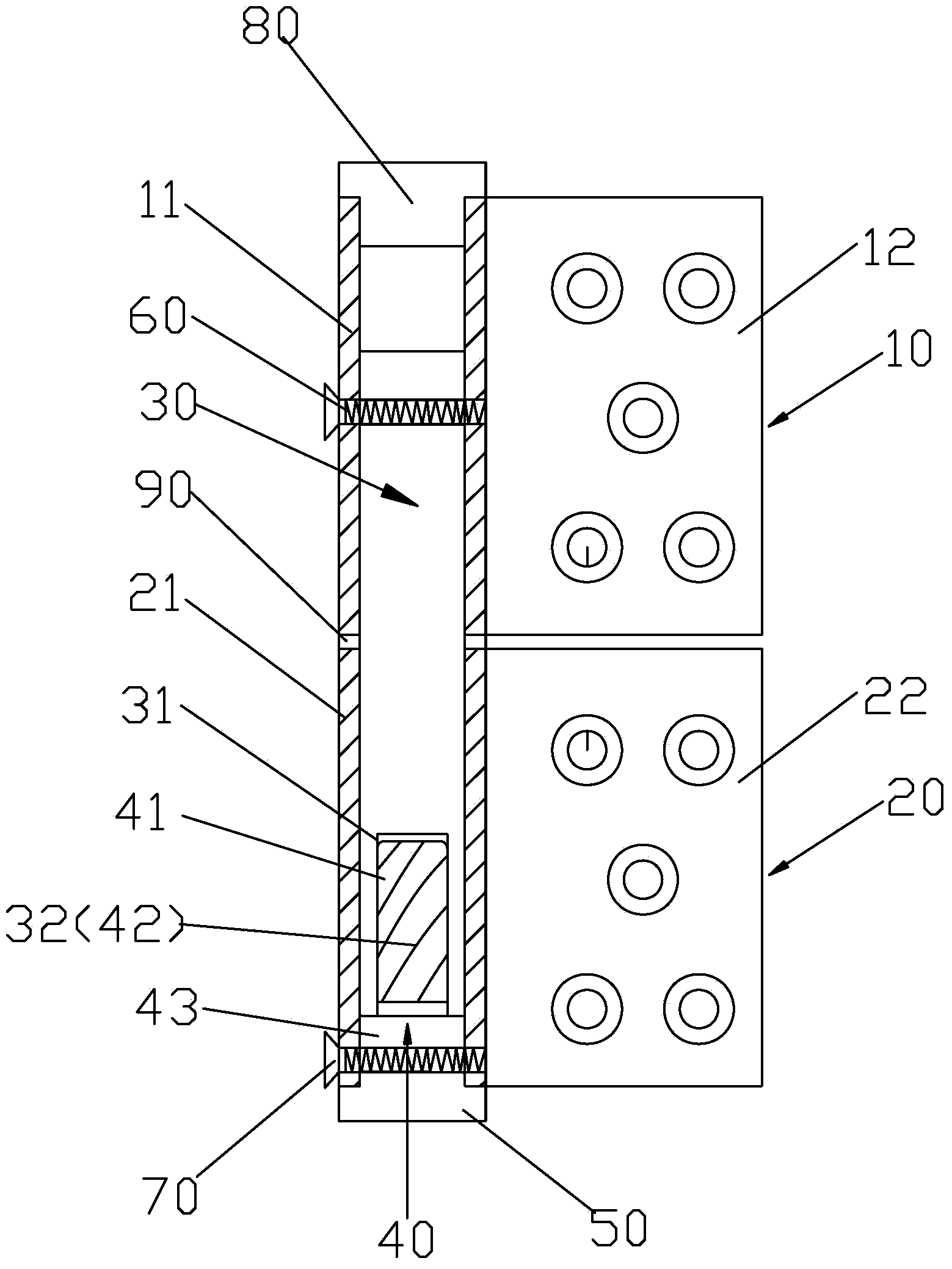
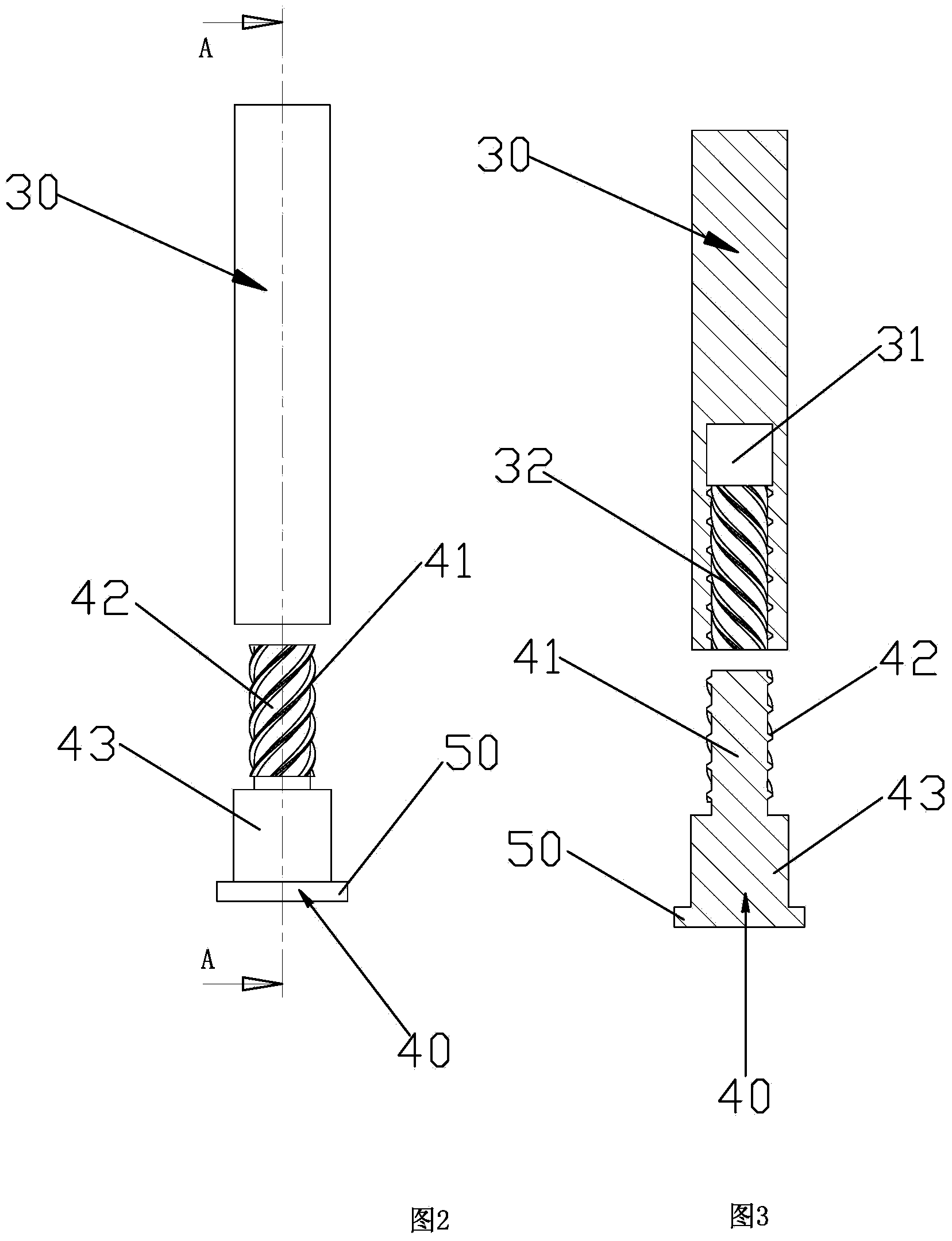
[0046] Please check figure 1 , figure 2 and image 3 , The lifting hinge device, such as the lifting self-closing device, includes an upper hinge 10, a lower hinge 20, a transmission seat 30 and a transmission rod 40.

[0047] The upper hinge 10 includes an upper shaft sleeve 11 and an upper hinge piece 12 fixedly connected to the upper shaft sleeve 11 . The lower hinge 20 includes a lower shaft sleeve 21 and a lower hinge piece 22 fixedly connected to the lower shaft sleeve 21 . In this embodiment, the upper bushing 11 and the upper hinge piece 12 are of the same length and arranged flush with the ends, and the lower bushing 21 and the lower hinge piece 22 are of the same length and arranged with the ends flush with each other. The upper hinge piece and the lower hinge piece are provided with mounting holes for installing door panels or window panels.

[0048]The transmission seat 30 is adapted and fixed in the upper shaft sleeve 11. The adaptation is that the outer diam...

Embodiment 2

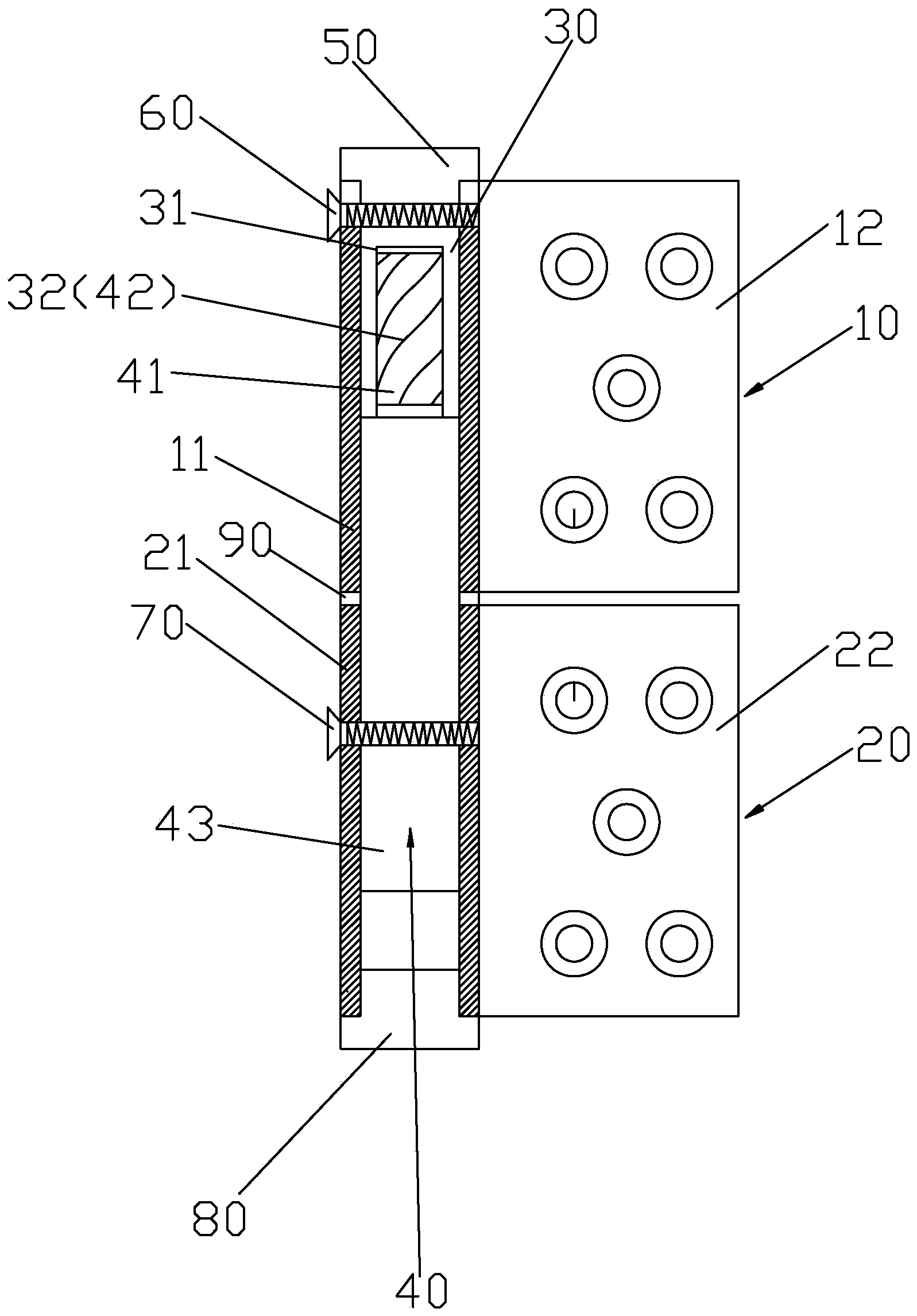
[0054] It differs from Embodiment 1 in that: Please refer to Figure 4 , Figure 5 and Figure 5-1 , the upper part of the solid seat 43 protrudes above the lower bushing 21, and the upper bushing 11 is adapted to be movably socketed outside the upper part of the solid seat 43. The fixed seat 43 of the transmission rod 40 is used to ensure the accuracy of the rotation of the hinge device. The transmission seat 30 is adapted to be fixed in the upper shaft sleeve 11, and a plug seat 50 is fixed at the end of the transmission seat 30. The outer diameter of the plug seat 50 is larger than the outer diameter of the transmission seat 30. The annulus outside the seat 30, the annulus is adapted to lean against the top end surface of the upper bushing, and the outer diameter of the plug seat is compatible with the outer diameter of the upper bushing. The plug 80 is attached to the lower port of the lower sleeve.

[0055] The check Figure 5 , wherein, the first helical part 32 and...

Embodiment 3

[0057] It differs from Embodiment 1 in that: Please refer to Figure 6 , Figure 7 and Figure 7-1 , the transmission rod 40 is fixedly connected in the upper shaft sleeve 11 , and the outer rotating surface of the transmission rod 40 is provided with a second helical part 42 . The transmission seat 30 is fixedly connected in the lower shaft sleeve 21 , the top surface of the transmission seat 30 is concavely provided with a transmission chamber 31 , and the inner rotating surface of the transmission chamber 31 is provided with a first helical part 32 . The upper part of the transmission seat 30 protrudes above the lower shaft sleeve 21, and the upper shaft sleeve is also movably sleeved outside the upper part of the transmission seat. The upper end of the transmission rod 40 is fixed with a plug seat 50, that is, the plug seat 50 is fixed on the solid seat 43, and the outer diameter of the plug seat 50 is greater than the outer diameter of the solid seat 43. The annulus ou...


PUM


Abstract

The invention discloses a liftable hinge device. The liftable hinge device comprises an upper hinge, a lower hinge, a transmission base and a transmission rod, wherein the upper hinge comprises an upper shaft sleeve and an upper hinge sheet fixedly connected with the upper shaft sleeve; the lower hinge comprises a lower shaft sleeve and a lower hinge sheet fixedly connected with the lower shaft sleeve; the transmission base is fixedly connected with the upper shaft sleeve; a transmission cavity is concavely formed in the bottom end surface of the transmission base; a first spiral part is arranged on an internal rotary surface of the transmission cavity; the transmission rod is fixedly connected with the lower shaft sleeve; a second spiral part is arranged on an external rotary surface of the transmission rod; the transmission rod is connected with the transmission cavity; the first spiral part is adapted and meshed with the second spiral part; the upper hinge is pushed to rotate relative to the lower hinge, and the upper hinge is lifted through matching of the first spiral part and the second spiral part; a pushing action is released to decline the upper hinge under the action of gravity, and the upper hinge can automatically return to a closed state through matching of the first spiral part and the second spiral part. The liftable hinge device has the advantages of low cost, high connection strength, high stability, difficult damage, long service life and attractive appearance.

Description

technical field [0001] The invention relates to a lifting hinge device. Background technique [0002] In order to realize the automatic closing of the door, two kinds of self-closing leaf devices are disclosed in the prior art. [0003] The first type is a self-closing device, including an upper hinge, a lower hinge and a shaft core. The upper hinge includes an upper shaft sleeve and an upper hinge piece fixedly connected to the upper shaft sleeve, and the lower hinge includes a lower shaft sleeve and a lower hinge piece fixedly connected to the lower shaft sleeve. The shaft core is arranged in the upper shaft sleeve and the lower shaft sleeve, and the shaft core and the lower shaft sleeve are fixedly connected, and the upper shaft sleeve can be movably connected outside the shaft core. In order to realize automatic closing, an elastic body is arranged between the shaft core and the upper shaft sleeve. Push the upper hinge to make the upper hinge rotate relative to the lo...

Claims


Application Information

Patent Timeline
Patent Type & Authority Applications(China)
IPC IPC(8): E05F1/06
Inventor 吴裕龙赵芬
Owner 吴裕龙
Why Eureka
Try Eureka