Centrifugal compressor

A technology of centrifugal compressors and centrifuges, which is applied in the direction of mechanical equipment, engine manufacturing, machines/engines, etc., can solve the problems of reduced stable working range, enlarged axial dimension, and increased number of parts, so as to achieve stable working range, shaft The effect of small size and low number of parts

Active Publication Date: 2015-02-11
BEIJING POWER MACHINERY INST
View PDF3 Cites 23 Cited by
  • Summary
  • Abstract
  • Description
  • Claims
  • Application Information

AI Technical Summary

Problems solved by technology

The increase in the number of stages leads to an increase in the number of parts, an inc...

Method used


Image

  • Centrifugal compressor
  • Centrifugal compressor
  • Centrifugal compressor

Examples


Embodiment Construction

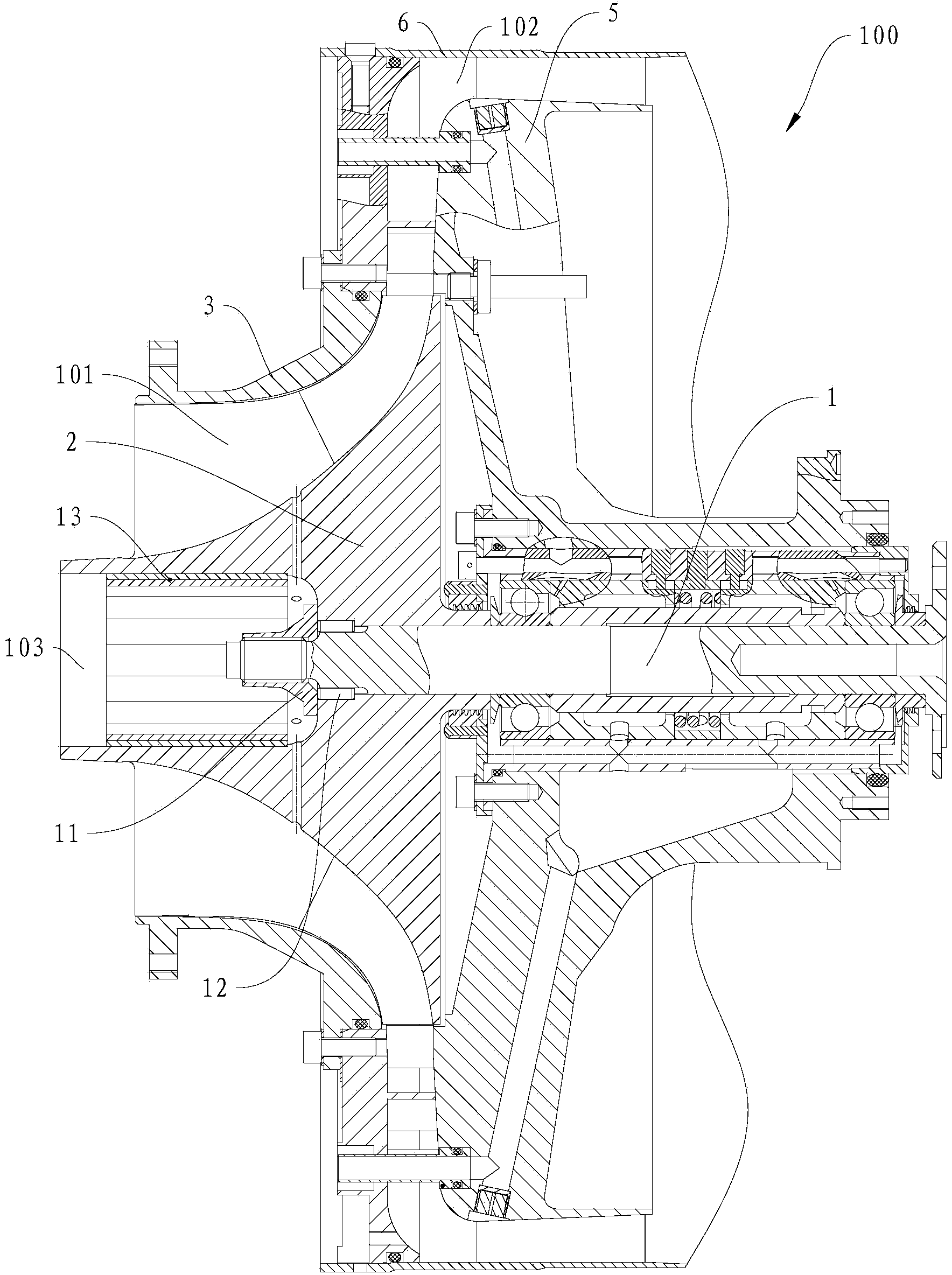
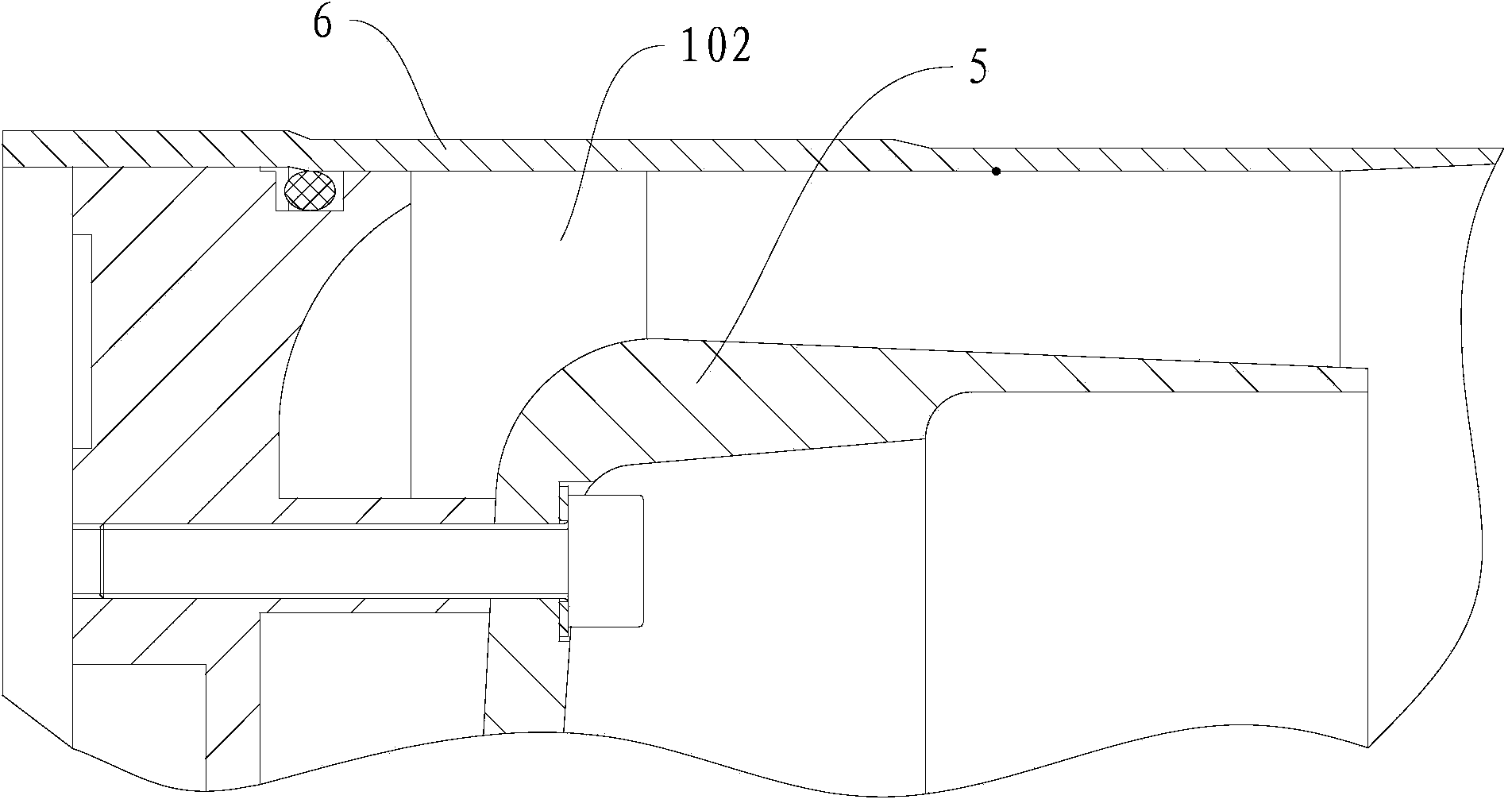
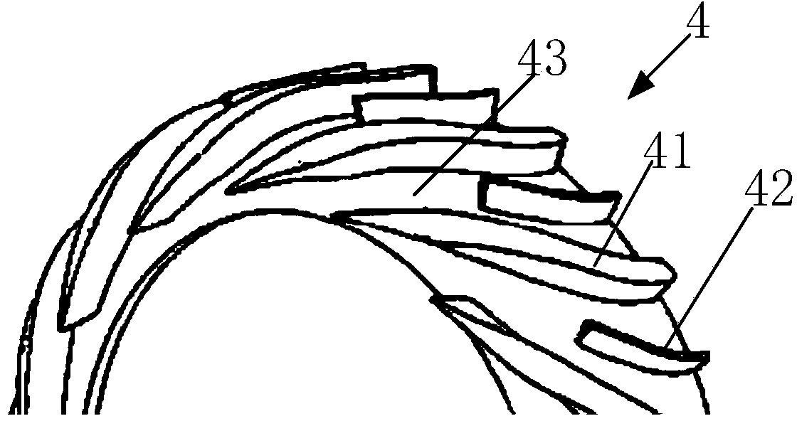
[0021] Embodiments of the present invention are described in detail below, examples of which are shown in the drawings, wherein the same or similar reference numerals designate the same or similar elements or elements having the same or similar functions throughout. The embodiments described below by referring to the figures are exemplary and are intended to explain the present invention and should not be construed as limiting the present invention.

[0022] In describing the present invention, it should be understood that the terms "center", "longitudinal", "transverse", "length", "width", "thickness", "upper", "lower", "front", " Orientation or position indicated by "back", "left", "right", "vertical", "horizontal", "top", "bottom", "inner", "outer", "clockwise", "counterclockwise", etc. The relationship is based on the orientation or positional relationship shown in the drawings, and is only for the convenience of describing the present invention and simplifying the descrip...


PUM


Abstract

The invention discloses a centrifugal compressor. The centrifugal compressor comprises a central spindle, a centrifugal vane wheel, a centrifugal machine box, a continuous pressure expander and a pressure expander machine box, wherein the centrifugal vane wheel is arranged on the central spindle in a sleeving mode; the centrifugal machine box is arranged around the centrifugal vane wheel, and a first airflow passage is formed between the centrifugal machine box and the centrifugal vane wheel; the continuous pressure expander is connected with the centrifugal vane wheel and is positioned at the outlet of the first airflow passage, and the continuous pressure expander is a vane pressure expander; the pressure expander machine box is connected with the centrifugal machine box and surrounds the continuous pressure expander, and a second airflow passage communicated with the first airflow passage is formed between the pressure expander machine box and the continuous pressure expander. According to the centrifugal compressor in the embodiment, due to the adoption of a centrifugal structure, the disadvantage of an axial-flow compressor on the application of a small turbojet engine is overcome. Meanwhile, with the structure, the amount of components is reduced relative to a traditional centrifugal compressor.

Description

technical field [0001] The invention relates to the technical field of compressor manufacturing, in particular to a centrifugal compressor. Background technique [0002] The centrifugal compressor has been widely used in small turbojet engines due to its high single-stage boosting ratio, simple structure, few parts, small axial size, and wide stable working range. With the development of modern military theory, small turbojet engines are facing great demand as power devices for missiles and unmanned aerial vehicles. At present, most of the small turbojet engines that have been successfully developed in China still use axial flow compressors. Compared with the centrifugal compressor, the single-stage pressure ratio of the axial flow compressor is lower, and more stages are required to achieve the same pressure ratio. The increase in the number of stages leads to an increase in the number of parts, an increase in the axial dimension, a complex structure, and a reduction in t...

Claims


Application Information

Patent Timeline
IPC IPC(8): F04D29/44
CPCF04D29/448F05D2250/52F04D29/444
Inventor 蔡文哲陆瑶张哲马同玲
Owner BEIJING POWER MACHINERY INST
Why Eureka
Try Eureka