
Eureka
For R&D, Eureka makes reading and utilizing patents & technical documents easy.
Eureka AIR
Designed for self-driven R&D workflows. Generate viable solutions, solve complex R&D challenges, empower your innovation with AI.

Eureka Materials
Designed for material experts only. Revolutionize your material R&D, from search, analyze, to developing new materials.

TechResearch
Generate reliable direction feasibility study reports for your R&D in just a few steps.

TechSeek
Discover and master advanced knowledge NOW. Basics, ideas, possibilities, all at once.

TechMind
As an expert in R&D Theories, TechMind can generates customized viable solutions instantly.

TechRisk
Analyze your overall solution with one click, know your potential R&D risks in advance.

TechMonitor
Get weekly tech updates, stay abreast of the latest tech innovations and key insights.
Oil separator
An oil separator and oil separation technology, which is applied in the field of separators, can solve the problems of insufficient filtering effect and small filtering area, and achieve the effect of improving filtering effect, increasing filtering area, and increasing filtering times
- Summary
- Abstract
- Description
- Claims
- Application Information
AI Technical Summary
Problems solved by technology
Method used
Image

Examples
Embodiment Construction
[0024] In order to make the object, technical solution and advantages of the present invention clearer, the oil separator of the present invention will be further described in detail below with reference to the accompanying drawings and embodiments. It should be understood that the specific embodiments described here are only used to explain the present invention, not to limit the present invention.
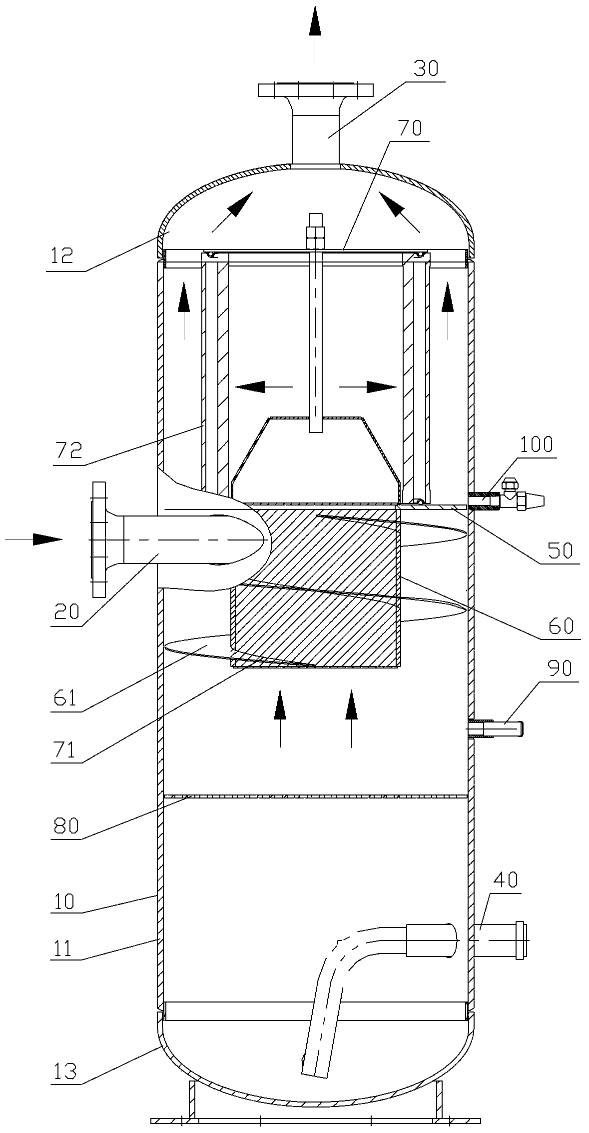
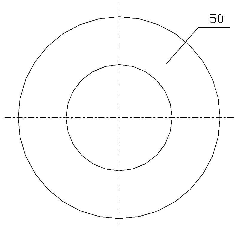
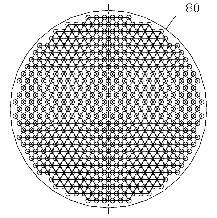
[0025] refer to Figure 1 to Figure 3 , an embodiment of the oil separator of the present invention includes a housing 10 with an inner cavity, the housing 10 is provided with an oil inlet 20, an oil outlet 30 and a first oil return port 40, and the inner wall of the housing 10 is connected with a sealing plate 50 and a porous baffle 80, the sealing plate 50 and the porous baffle 80 divide the inner chamber into a first space communicated with the oil outlet 30, a second space communicated with the oil inlet 20, and a second space communicated with the first oil return port 40 I...
PUM
 Abstract
Description
Claims
Application Information
 - R&D Engineer
- R&D Manager
- IP Professional
- Industry Leading Data Capabilities
- Powerful AI technology
- Patent DNA Extraction
Browse by: Latest US Patents, China's latest patents, Technical Efficacy Thesaurus, Application Domain, Technology Topic, Popular Technical Reports.
© 2024 PatSnap. All rights reserved.Legal|Privacy policy|Modern Slavery Act Transparency Statement|Sitemap|About US| Contact US: help@patsnap.com