Processing cartridge

A process cartridge and electronic imaging technology, applied in the field of process cartridges

Inactive Publication Date: 2015-02-11
NINESTAR CORP
View PDF5 Cites 10 Cited by
  • Summary
  • Abstract
  • Description
  • Claims
  • Application Information

AI Technical Summary

Problems solved by technology

[0005] The invention provides a processing box to solve the technical problem that the existing processing box needs to rely on the door cover of the electronic imaging device to close the door to realize the function of the pressing rod

Method used


Image

  • Processing cartridge
  • Processing cartridge
  • Processing cartridge

Examples


Embodiment 1

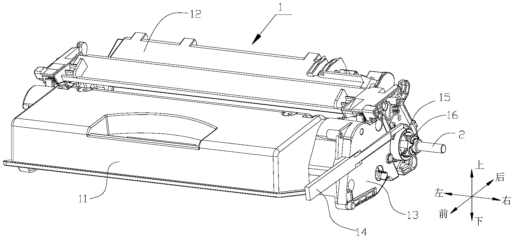
[0031] figure 1 It is a perspective view of a process cartridge using a positioning ring scheme in the prior art, 1 is a process cartridge, including a process cartridge housing, and the process cartridge housing includes a developer accommodating part 11 for accommodating developer and a part 12 for accommodating waste developer.

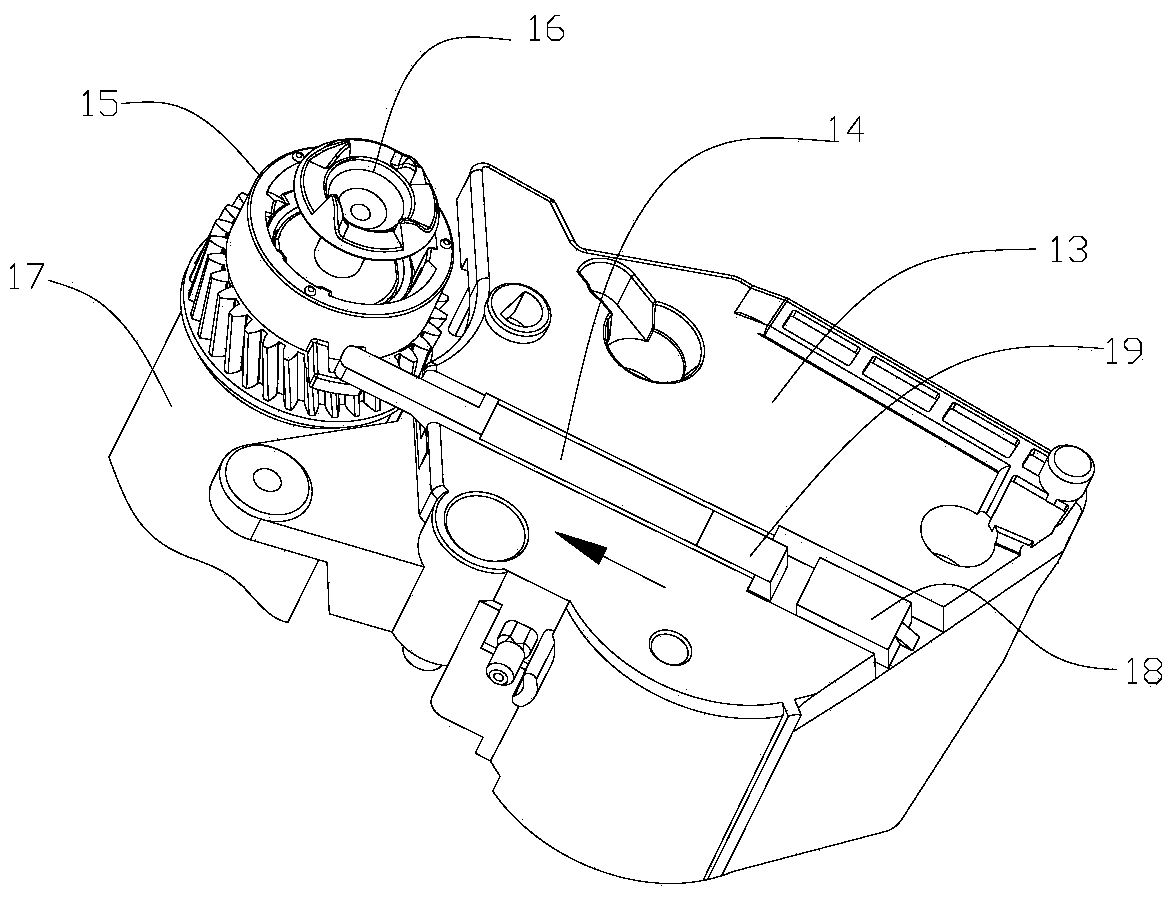
[0032] On the developer accommodating portion 11 is placed a developing roller or magnet roller (not shown in the figure) for transferring the developer. A photosensitive element (such as figure 2 Shown photosensitive element 17), and a charging element (not shown) for charging the photosensitive element.

[0033] One end in the axial direction of the photosensitive element 17 is provided with a rotational power receiving head 16 that engages with the rotational force driving head 2 provided in the electronic imaging device to receive power, and assists the positioning of the rotational power receiving head 16 in the axial direction of the photos...

Embodiment 2

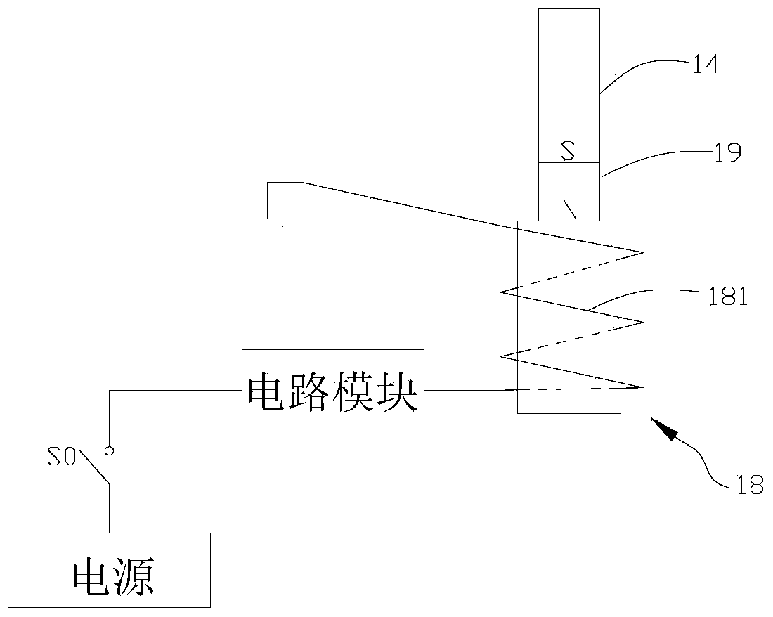
[0046] In the first embodiment, the extension of the pressing rod 14 is controlled by the electromagnet, so that the positioning ring 15 rotates, and drives the rotation power receiving head 16 to protrude along the axis of the photosensitive element and meshes with the rotation force driving head 2 to transmit power. However, in this implementation, the pressing rod can be attracted after the electromagnet is energized, and the rotating power receiving head is urged to protrude along the axis direction of the photosensitive element after the positioning ring is also rotated. The mechanism connected with the rotary power receiving head does not need to be changed, only the pressing rod 14 needs to be placed in a position symmetrical to the axis of the photosensitive element with respect to the position of the pressing rod in Embodiment 1, as Image 6 shown.

[0047] In this embodiment, the permanent magnet 19 provided at the end of the pressing rod in the embodiment is replace...


PUM


Abstract

The invention relates to a processing cartridge which can be detachably mounted in an electronic imaging device. A rotary power driving head is arranged inside the electronic imaging device. The processing cartridge comprises a processing cartridge shell and a photosensitive element used for bearing an image carrier, wherein a rotary driving power receiving head, which is meshed with the rotary power driving head in the electronic imaging device and used for transmitting the rotary power to the photosensitive element, is arranged at one end of the photosensitive element; a pressing rod used for enabling the rotary driving power receiving head to move in the axial direction of the photosensitive element is arranged at one end of the processing cartridge; and the processing cartridge also comprises a pressing rod control mechanism which is arranged at the end of the processing cartridge shell and is connected with one end of the pressing rod so as to control the pressing rod to move. By virtue of the processing cartridge, the technical problem that the function of the pressing rod can be implemented by closing a cover and a door of the existing processing cartridge by means of the electronic imaging device can be solved.

Description

technical field [0001] The present invention relates to a process cartridge for an electronic image forming apparatus. Background technique [0002] A prior art process cartridge is detachably mounted in an electronic imaging device. The electronic imaging device is provided with a rotational force driving head. The process box includes a photosensitive element for carrying an image carrier, and a photosensitive element gear arranged at one end of the photosensitive element, and the photosensitive element gear is provided with a gear that can be engaged with the rotational force driving head in the electronic imaging device. Rotational power is transmitted to the rotational driving force receiving head of the photosensitive element. [0003] Chinese patent CN201010131386.1 discloses a process cartridge, the process cartridge is provided with a photosensitive element power transmission device engaged with a driving mechanism (ie, the rotational force driving head) to drive ...

Claims


Application Information

Patent Timeline
Patent Type & Authority Applications(China)
IPC IPC(8): G03G21/18
CPCG03G21/1842
Inventor 罗来曹建新
Owner NINESTAR CORP
Why Eureka
Try Eureka