Connection terminals, sealed connection terminals and connectors

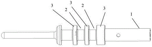
A technology for connecting terminals and connectors, which is applied in the direction of connection, parts and contact parts of connecting devices, etc., can solve the problem that the connecting terminal 1 is difficult to insert into the accommodating hole, the O-ring is squeezed, and the sealing effect cannot be achieved, etc. problem, to achieve the effect of simple structure, ensuring sealing effect and cost saving

Inactive Publication Date: 2017-05-03
TYCO ELECTRONICS (SHANGHAI) CO LTD
View PDF4 Cites 0 Cited by
  • Summary
  • Abstract
  • Description
  • Claims
  • Application Information

AI Technical Summary

Problems solved by technology

However, the O-shaped sealing ring protrudes more than the connecting terminal 1. When the connecting terminal 1 is inserted into the accommodation hole, the inner wall of the accommodation hole has a greater friction force on the O-shaped sealing ring, which will cause the O-shaped sealing ring to shift and go out. The groove 2 is squeezed in the narrow gap between the shoulder 3 and the inner wall of the accommodating hole, making it difficult for the connecting terminal 1 to be inserted into the accommodating hole
In severe cases, the excessive extrusion force will crush the O-ring, and the proper sealing effect cannot be achieved.

Method used


Image

  • Connection terminals, sealed connection terminals and connectors
  • Connection terminals, sealed connection terminals and connectors
  • Connection terminals, sealed connection terminals and connectors

Examples


Embodiment 1

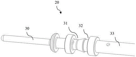
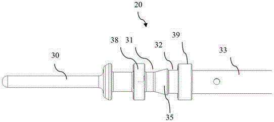
[0064] Such as figure 2 , 3 As shown in and 4, the connection terminal 20 includes a terminal body 30 for electrical connection with a mated terminal. The terminal body 30 is a cylinder. The terminal body 30 is provided with first accommodating grooves 31 and second accommodating grooves 32 distributed along the length direction. The connection terminal 20 also includes a wiring body 33 for connecting a wire end (not shown in the figure). in such as Figure 4 In the example shown, the terminal body 33 is provided with an axial cavity 33a for receiving a wire end.

[0065] Such as figure 2 , image 3 and Figure 4 As shown in , both the first accommodating groove 31 and the second accommodating groove 32 are arranged for one circle along the circumferential direction of the terminal body 30 . From image 3 In the front view direction of the connecting terminal shown, the first accommodating groove 31 and the second accommodating groove 32 can extend from the surface ...

Embodiment 2

[0069] Such as Figure 5A , Figure 5B and Figure 6 As shown, the sealed connection terminal 40 includes the connection terminal 20 and a sealing ring 50 . The sealing ring 50 is sleeved on the connecting terminal 20 .

[0070] Such as figure 2 , image 3 and Figure 4 As shown, the connection terminal 20 includes a terminal body 30 . The terminal body 30 is a cylinder. The terminal body 30 is provided with first accommodating grooves 31 and second accommodating grooves 32 distributed along the length direction. The connection terminal 20 also includes a wiring body 33 for connecting a wire end (not shown in the figure).

[0071] Both the first accommodating groove 31 and the second accommodating groove 32 are arranged for one circle along the circumferential direction of the terminal body 30 . The first accommodating groove 31 and the second accommodating groove 32 can either extend from the surface of the terminal body 30 to the axial direction and be lower than t...

Embodiment 3

[0077] Such as Figure 7 , Figure 8 and Figure 9 As shown, the connector 60 includes a housing 70 and a sealed connection terminal 40 . The casing 70 is provided with a receiving hole 71 . The sealed connection terminal 40 is inserted into the accommodation hole 71 .

[0078] The sealed connection terminal 40 includes the connection terminal 20 and a sealing ring 50 . The sealing ring 50 is sleeved on the connecting terminal 20 .

[0079] Such as figure 2 , image 3 and Figure 4 As shown, the connecting terminal 20 includes a terminal body 30 . The terminal body 30 is a cylinder. The terminal body 30 is provided with first accommodating grooves 31 and second accommodating grooves 32 distributed along the length direction. Both the first accommodating groove 31 and the second accommodating groove 32 are arranged for one circle along the circumferential direction of the terminal body 30 . The first accommodating groove 31 and the second accommodating groove 32 can...


PUM


Abstract

The invention discloses a connection terminal, a tight connection terminal and a connector, and discloses the connection terminal. The connection terminal is characterized by comprising a terminal body, wherein a first containing groove and a second containing groove are distributed in the terminal body along the length direction, respectively surround the terminal body by a circle, and are used for containing a sealing ring; when the sealing ring arranged in the first containing groove is stressed, the sealing ring can move into the second containing groove from the first containing groove and is kept in the second containing groove. The connection terminal disclosed by the invention can guide the sealing rings to move in the process of being inserted into a containing hole by the structure arrangement, the connection terminal can be ensured to be smoothly inserted into the containing hole of a shell, and the O-shaped sealing ring does not step over the corresponding groove to reduce the sealing effect. The sealing ring is guided to move, and can be prevented from being damaged in the process of inserting the connection terminal into the containing hole, and thus the sealing effect is ensured.

Description

technical field [0001] The invention relates to a connection terminal, a sealed connection terminal and a connector. Background technique [0002] Connecting terminals are generally used in connectors for electrical connection with connecting terminals in mating connectors. The terminals are fixed in the housing holes. Such as figure 1 A sealed connection terminal 1 is shown, which is provided with two grooves 2 . An O-ring (not shown in the figure) is arranged in each groove 2 . The two axial sides of each groove 2 are provided with shoulders 3 for restricting the O-ring in the groove 3 . When in use, the connecting terminal 1 is inserted into the housing hole, and the O-ring is used to seal the gap between the connecting terminal 1 and the inner wall of the housing hole. In order to enhance the sealing effect, the O-ring usually protrudes more than the connection terminal 1 . However, before the connecting terminal 1 is inserted into the accommodating hole, the O-rin...

Claims


Application Information

Patent Timeline
Patent Type & Authority Patents(China)
IPC IPC(8): H01R13/02H01R13/52
CPCH01R13/02H01R13/213H01R13/5202
Inventor 余见能袁伟张萌羽许磊磊章皓程
Owner TYCO ELECTRONICS (SHANGHAI) CO LTD
Why Eureka
Try Eureka