
A high-efficiency solar-powered hybrid vehicle charging station

A technology for hybrid electric vehicles and solar panels, applied in charging stations for mobile devices, electric vehicles, and data exchange chargers, etc., can solve the problems of relying on traditional energy sources, slow cost recovery benefits, and low conversion efficiency, and achieve improved System energy transmission, output power gain is obvious, and the effect of improving charging efficiency

Active Publication Date: 2017-02-15
深圳市索阳新能源科技有限公司
View PDF9 Cites 0 Cited by
  • Summary
  • Abstract
  • Description
  • Claims
  • Application Information

AI Technical Summary

Problems solved by technology

[0005] 1. The existing electric vehicle charging station is basically connected to the mains or uses a small amount of solar power to generate electricity, which is costly and is also affected by power outages in the grid;
[0006] 2. The power supply of the existing electric vehicle charging station is unstable, which puts a lot of pressure on the power grid during the peak period of power consumption during the day;
[0007] 3. The existing electric vehicle charging station facilities are not flexible enough and cannot be used in remote power-deficient areas;
[0008] 4. The existing electric vehicle charging stations rely too much on traditional energy sources;
[0009] 5. The cost of traditional electric vehicle charging stations is high, and the cost recovery benefits are slow;
[0010] 6. Traditional electric vehicle charging stations use conventional solar modules with low conversion efficiency
[0014] However, the above-mentioned patents all have the defects of high cost and slow cost recovery benefits; at the same time, the solutions of the above-mentioned patents all use conventional solar modules, and their conversion efficiency is low

Method used


Image

  • A high-efficiency solar-powered hybrid vehicle charging station
  • A high-efficiency solar-powered hybrid vehicle charging station
  • A high-efficiency solar-powered hybrid vehicle charging station

Examples


Embodiment 1

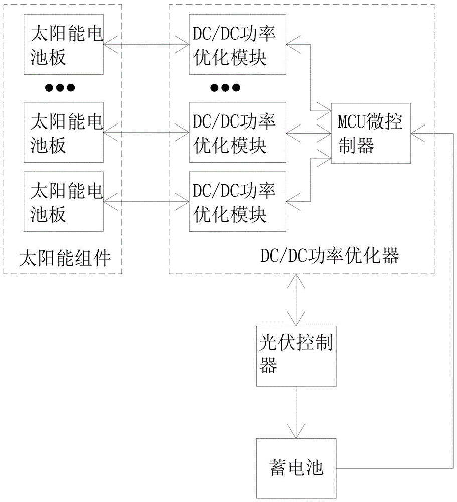
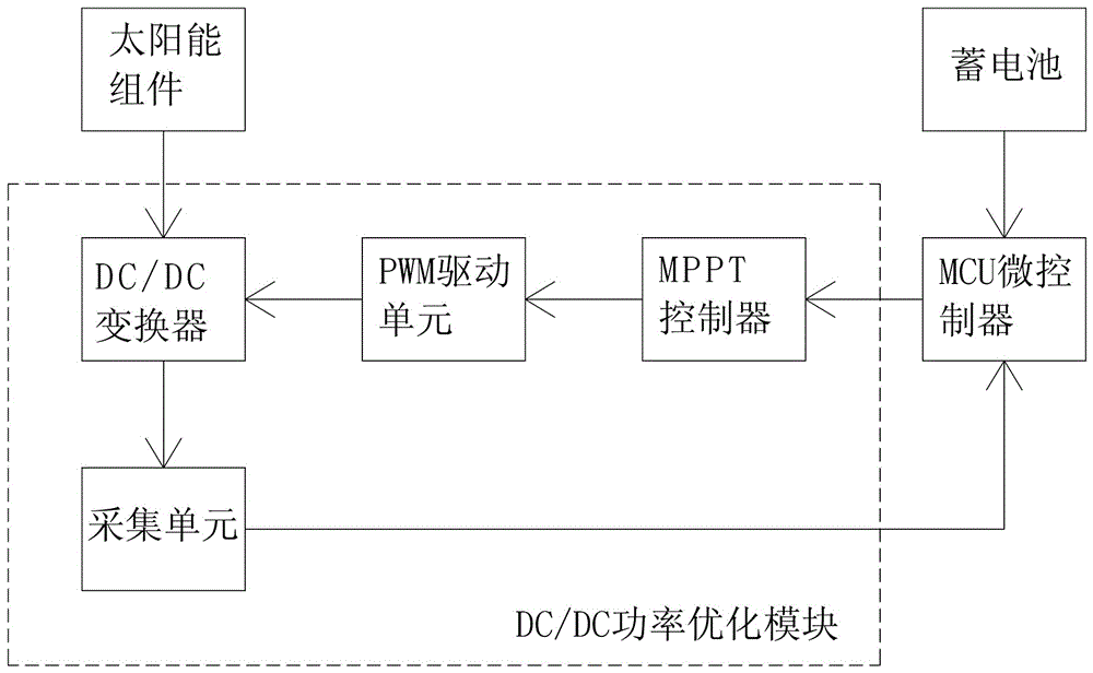
[0045] As a specific embodiment, a high-efficiency solar hybrid vehicle charging station of the present invention includes a steel structure carport support, a solar module is arranged on the upper part of the steel structure carport support, and several charging piles are fixedly arranged on the steel structure carport support. There is a battery in the charging pile, see figure 1 , the output of the solar module is connected to the input of the DC / DC power optimizer, the input and output of the DC / DC power optimizer are electrically connected to the input and output of the photovoltaic controller, and the output of the photovoltaic controller is connected to the battery input. Among them, the solar module includes a solar panel bracket, and several solar panels are fixed on the solar panel bracket, and the solar panel is provided with multiple parallel battery modules in series; the DC / DC power optimizer includes an MCU microcontroller and several Each DC / DC power optimizat...

Embodiment 2

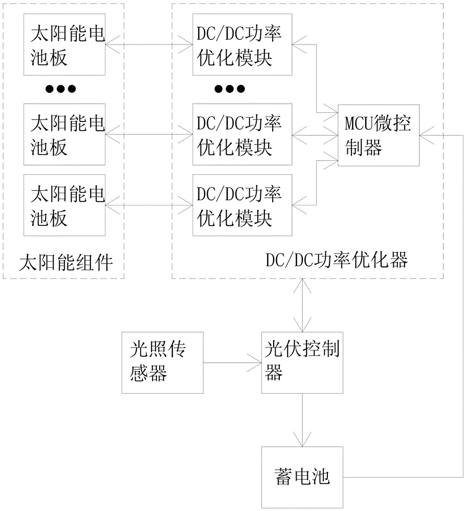
[0054] In this embodiment, different from Embodiment 1, the high-efficiency solar hybrid vehicle charging station also includes a light sensor for detecting light intensity, the light sensor is arranged on the solar panel support, and is consistent with the installation angle of the solar battery panel, see image 3 , the output terminal of the light sensor is connected to the input terminal of the photovoltaic controller.

[0055] The intelligent control system controls the operation of the entire system, see Figure 4 , in addition to the various processes in Embodiment 1, step 4 of which also includes the following process: if a vehicle enters, the intelligent control system judges whether the solar module can work through the light intensity obtained by the light sensor and the preset threshold, if not If it is working, the accumulator is controlled to charge the incoming vehicle directly.

[0056] In addition, the intelligent control system can be expanded arbitrarily, ...

Embodiment 3

[0059] The battery is an important part of the DC power supply system in the power supply system. When charging the battery, the traditional centralized system is generally used at present. When the photovoltaic array is partially shaded by the centralized system, the efficiency of the entire system will drop sharply. .

[0060] In view of this deficiency, and in order to prolong the service life of the storage battery and rationally configure the power supply of the whole system to improve the system efficiency, see Figure 5 , in this embodiment, the high-efficiency solar hybrid electric vehicle charging station also includes a centralized controller for detecting battery voltage, the input terminal of the centralized controller is connected to the output terminal of the battery, and the input and output terminals of the centralized controller are connected to the DC / DC The input and output terminals of the MCU microcontroller of the power optimizer establish a communication...


PUM


Abstract

The invention discloses a high-efficiency solar charging station for hybrid vehicles. The high-efficiency solar charging station comprises a steel-structure shed bracket, wherein the upper part of the steel-structure shed bracket is provided with a solar component; a plurality of charging piles are also fixedly arranged on the steel-structure shed bracket and are internally provided with storage batteries; the output end of the solar component is connected with the input end of a DC / DC power optimizer; the input-output end of the DC / DC power optimizer is electrically connected with the input-output end of a photovoltaic controller; the output end of the photovoltaic controller is connected to the input ends of the storage batteries; the solar component comprises a solar battery panel bracket which is fixedly provided with a plurality of solar battery panels; the solar battery panels are provided with a plurality of battery components which are connected in series; the DC / DC power optimizer comprises an MCU (Micro Control Unit) and a plurality of DC / DC power optimization modules which are mutually and electrically connected; and the input-output end of each solar battery panel is electrically connected with the input-output end of one DC / DC power optimization module, and the MCU controls all the DC / DC power optimization modules.

Description

technical field [0001] The invention belongs to the field of solar charging equipment manufacturing, and more specifically relates to a solar hybrid electric vehicle charging station capable of charging electric vehicles or electric vehicles. Background technique [0002] With limited oil resources and increasing consumption, the skyrocketing price of oil is an inevitable phenomenon. At the same time, in the process of a large amount of oil consumption, the problem of environmental pollution also emerged. The discharge of harmful elements not only polluted the environment, but also caused harm to people's health problems to a large extent, destroying the living environment. The environment has seriously affected people's physical and mental health. Therefore, based on the important national conditions of the sustainable and harmonious development of the economy and society, we can easily find that the shortage of oil and the need for environmental protection have been restr...

Claims


Application Information

Patent Timeline
Patent Type & Authority Patents(China)
IPC IPC(8): H02J7/35
CPCH02J7/00036H02J7/0021H02J7/0027H02J7/00302H02J7/35Y02E10/56
Inventor 沈元仲沈亨春黄晓刚刘明轩
Owner 深圳市索阳新能源科技有限公司
Learn More