Filling machine and filling head

A filling head and filling machine technology, applied in packaging, bottle filling, liquid bottling, etc., can solve the problems of easy clogging of the filter screen 100, failure of filling, complex structure, etc., and achieve low cost and simple structure , The effect of smooth filling channel

Inactive Publication Date: 2015-02-18
GUANGZHOU TECH LONG PACKAGING MACHINERY CO LTD
View PDF6 Cites 4 Cited by
  • Summary
  • Abstract
  • Description
  • Claims
  • Application Information

AI Technical Summary

Problems solved by technology

[0002] When filling beverages containing pulp or fiber, traditional filling machines generally use such as figure 1 As shown in the filling head with filter 100, although the filling head with this structure can absorb the product without dripping when the valve is closed, the fiber or pulp is easy to block the filter 100, resulting in the failure of the next filling; Or use a structure with a spool to realize the opening and closing of the filling port by controlling the spool. This structure is complicated and the cost is high.

Method used


Image

  • Filling machine and filling head
  • Filling machine and filling head
  • Filling machine and filling head

Examples


Embodiment Construction

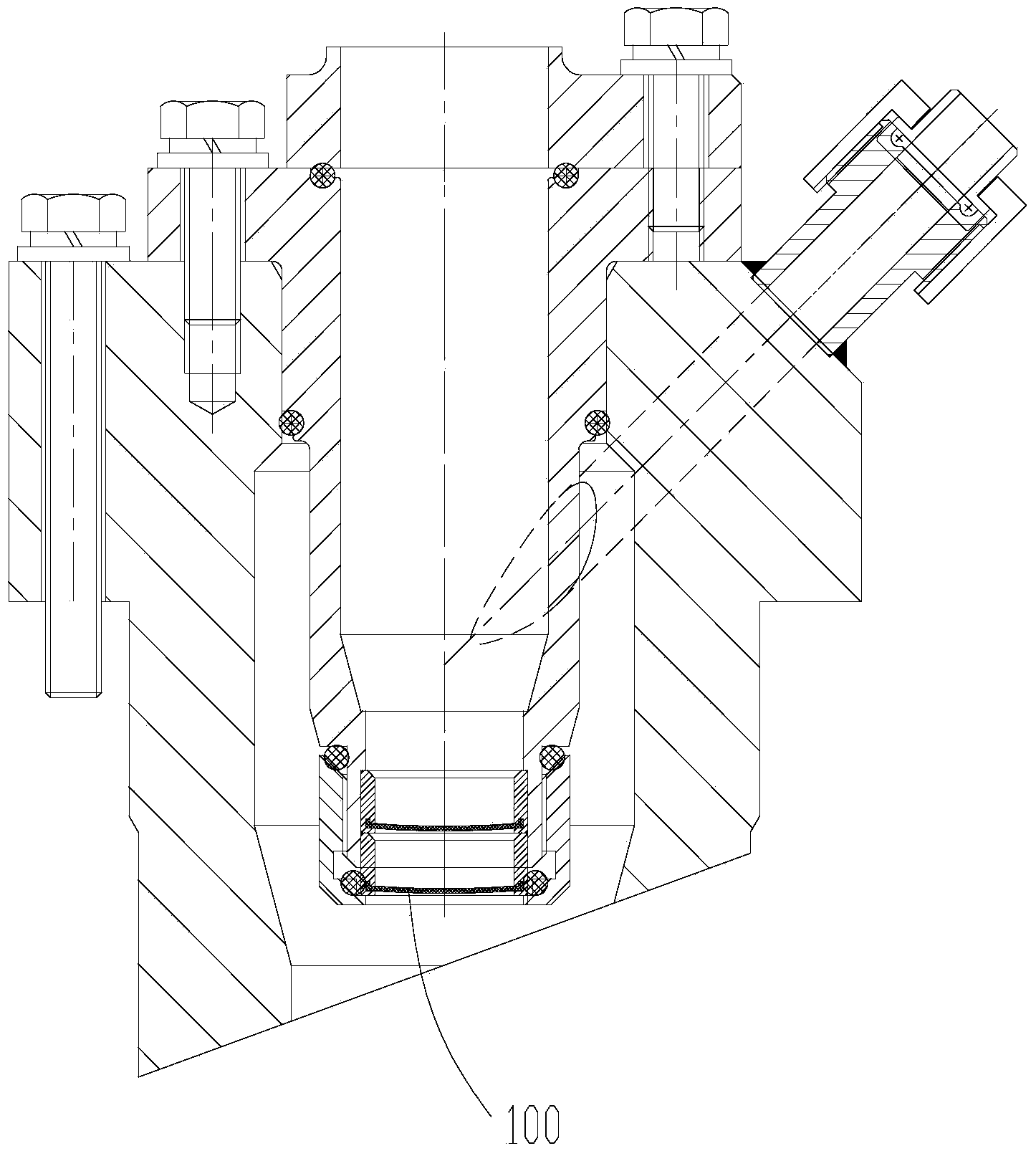
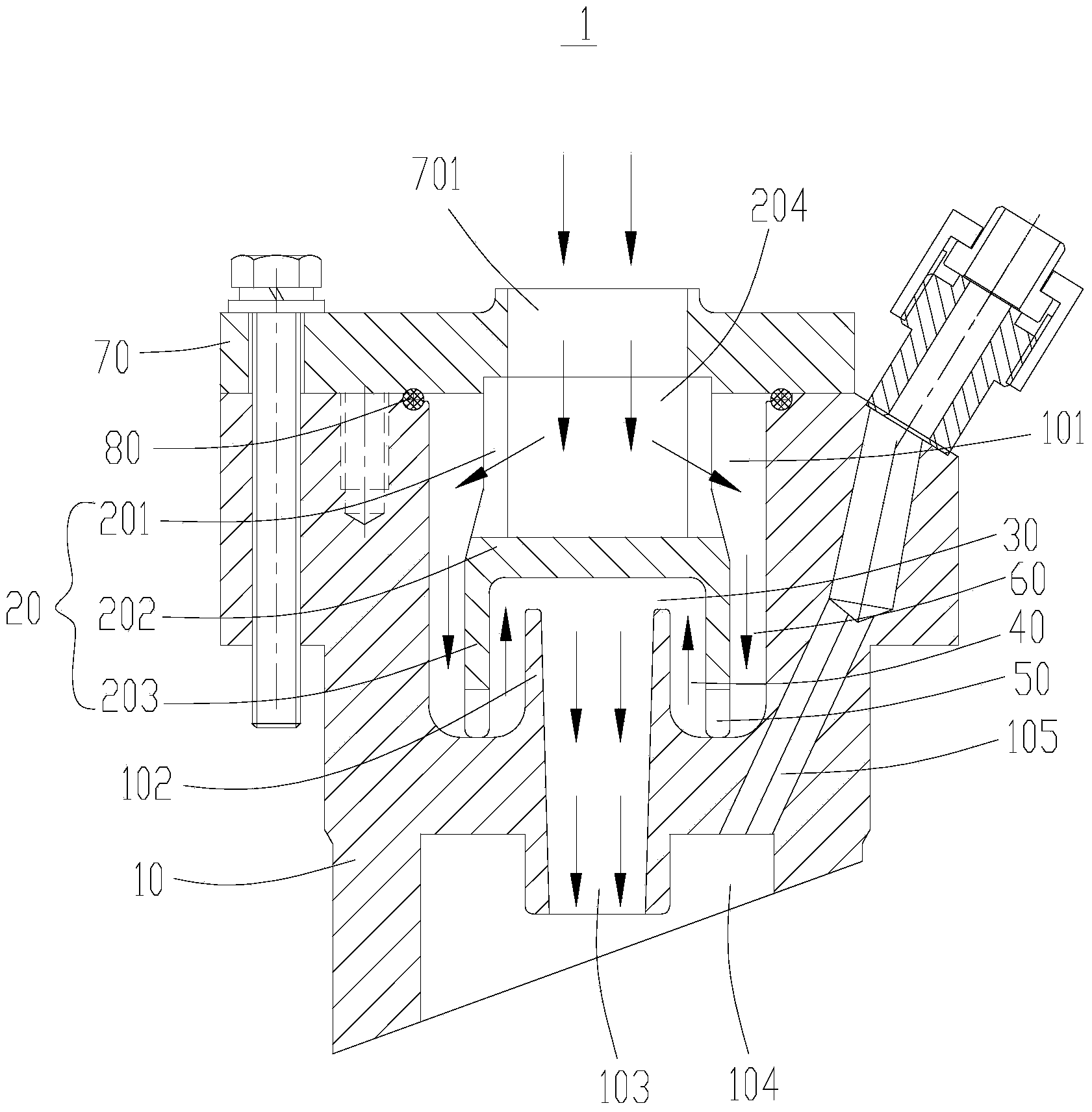
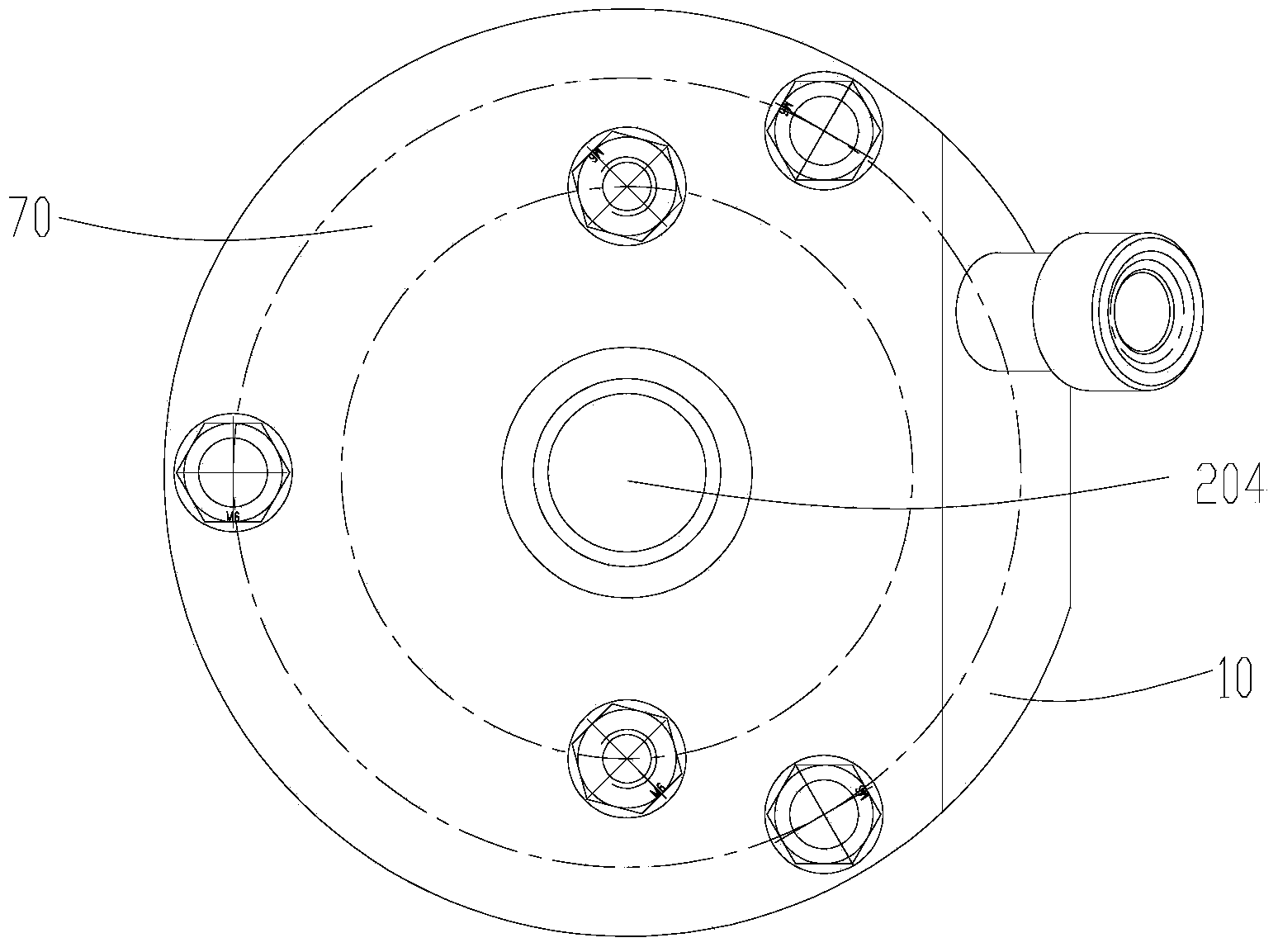
[0024] Such as figure 2 , image 3 As shown, a filling head 1 includes a hollow valve head body 10, the upper end of the valve head body is provided with an opening communicating with the inner cavity 101 of the valve head body, and the lower end inner wall of the valve head body is provided with An upward projection 102 is provided with an outlet 103 communicating with the internal cavity 101, and the internal cavity 101 is provided with a block 20, and the block 20 includes a connecting portion 201 connected in sequence, a first Blocking portion 202, second blocking portion 203, the connecting portion 201 is connected to the upper end of the valve head body, and the connecting portion 201 is provided with an inlet 204 matching the opening, the first blocking portion 202 is arranged on the Above the protrusion 102 , the second shielding portion 203 is disposed on a side of the protrusion 102 .

[0025] The filling head 1 described in this embodiment, by setting the block 2...


PUM


Abstract

The invention discloses a filling machine and a filling head. The filling head comprises a hollow valve head body, wherein an opening communicated with the internal cavity of the valve head body is formed in the upper end of the valve head body; an upward bulge is arranged on the inner wall of the lower end of the valve head body; an outlet communicated with the internal cavity is formed in the bulge; a clamping block is arranged in the internal cavity and comprises a connecting part, a first covering part and a second covering part which are connected in sequence; the connecting part is connected with the upper end of the valve head body; an inlet matched with the opening is formed in the connecting part; the first covering part is arranged above the bulge; the second covering part is arranged on the side edge of the bulge. As the outlet is formed in the bulge on the inner wall of the lower end of the valve head body, filling liquid remained in the internal cavity is blocked by the outer wall of the bulge and cannot flow out of the outlet when the filling operation is stopped, so that the dripping leakage of the residual liquid is effectively prevented; a filter net does not need to be arranged and the phenomenon of blocking the filter net by pulp and fibers cannot be caused.

Description

technical field [0001] The invention relates to filling equipment, in particular to a filling machine and a filling head. Background technique [0002] When filling beverages containing pulp or fiber, traditional filling machines generally use such as figure 1 As shown in the filling head with filter 100, although the filling head with this structure can absorb the product without dripping when the valve is closed, the fiber or pulp is easy to block the filter 100, resulting in the failure of the next filling; Alternatively, a structure with a spool is used to realize the opening and closing of the filling port by controlling the spool. This structure is complicated and the cost is high. Contents of the invention [0003] Based on this, it is necessary to address the defects of the prior art to provide a filling machine and a filling head, which can effectively prevent the product from dripping, and do not need to set a filter screen to avoid blockage caused by pulp and f...

Claims


Application Information

Patent Timeline
Patent Type & Authority Applications(China)
IPC IPC(8): B67C3/26B67C3/28
CPCB67C3/2608B67C3/287
Inventor 郑礼深杨恢光
Owner GUANGZHOU TECH LONG PACKAGING MACHINERY CO LTD
Why Eureka
Try Eureka