
locking pin

A technology of locking pins and pin bodies, which is applied to earth movers/excavators, construction, etc., can solve problems such as difficult assembly, short service life, and complex structure, and achieve easy assembly, reduced aging speed, and simple cooperation Effect

Active Publication Date: 2017-04-05
GUANGXI LIUGONG MASCH CO LTD
View PDF1 Cites 0 Cited by
  • Summary
  • Abstract
  • Description
  • Claims
  • Application Information

AI Technical Summary

Problems solved by technology

[0005] The purpose of the present invention is to provide a locking pin, which can solve the problems of existing locking pins with short service life, complex structure and difficult assembly

Method used


Image

  • locking pin
  • locking pin
  • locking pin

Examples


Embodiment 1

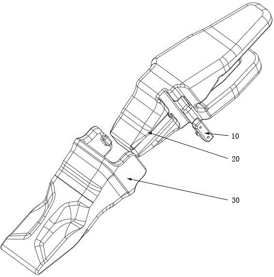
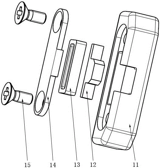
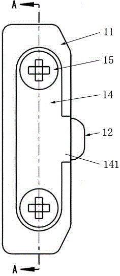
[0033] figure 1 The shown locking pin 10 is used to connect and fix the tooth holder 20 and the tooth body 30 of the excavator together, as figure 2 As shown, the locking pin 10 includes a pin body 11, a movable tenon 12, an elastic body 13, a cover plate 14 and a threaded connector 15, wherein the pin body 11 and the movable tenon 13 are both made of steel, and the elastic body 13 is made of rubber into; Figure 5 and Figure 6 As shown, the pin body 11 is a straight rod, and the straight rod is a straight quadrangular prism. The two ends of the pin body 11 are provided with grooves 115, so as to be easily inserted into the pin holes of the tooth body 30 and the gear holder 20. A rectangular groove 111 is provided on the side, and a cover plate 14 closing the notch of the groove 111 is installed and fixed on the pin body 11. The edge of the notch of the groove 111 is provided with a concave stop 113 for accommodating the cover plate 14, and a concave stop 113 The end face...

Embodiment 2

[0036] Such as Figures 11 to 13As shown, the limit portion 422 of the movable tenon 42 in this embodiment is an isosceles triangle plate, and the top corners and bottom corners of the cover limit portion 422 are all rounded; in order to facilitate the support of the movable pin, a There are two elastic bodies 43. The elastic bodies 43 in this embodiment are two oblique wedges arranged opposite to each other. The slopes 432 of the two oblique wedges are opposite. The opposite surfaces of the wedge are in contact with each other, and the remaining sides of the wedge are respectively in contact with the corresponding groove walls of the groove. The wedge is provided with a pit 431, see Figure 13 , to produce the desired deformation. All the other features are the same as in Example 1.


PUM


Abstract

The invention discloses a locking pin, and relates to the technical field of mechanical connecting components. The locking pin comprises a pin body, wherein the pin body is a straight rod, a groove is formed in the side of the pin body, a cover plate used for sealing the notch of the groove is mounted on the pin body, a movable tenon and an elastomer are clamped and arranged in a cavity which is formed by surrounding the cover plate and the groove, the movable tenon is provided with a tenon head which extends out of the pin body from the groove wall of the groove and limiting parts which are placed in the groove, one ends which are connected with the tenon head of the limiting parts are butted against to the groove wall of the groove, the free ends of the limiting parts are in butted connection to the elastomer, and the limiting parts and the elastomer are sealed in the cavity. Compared with the prior art, the locking pin disclosed by the invention has the advantages that the locking pin is more suitable for the severe environment, the service life is long, the structure is simple, the processing and the assembling are easy, the component replacement is convenient, and the usage cost is low.

Description

technical field [0001] The invention relates to the technical field of mechanical connectors, in particular to a pin for locking and fixing the tips of bucket teeth and the like to the joints of excavating equipment in the construction machinery industry, mining machinery and other fields. Background technique [0002] Excavators, loaders, and mining machines in the field of construction machinery and mining machinery excavate or reload with buckets, and the buckets play the role of cutting and loading materials. In order to reduce the insertion resistance and increase the cutting capacity of the bucket, it is necessary to install a bucket tooth assembly at the front of the bucket. Keep bucket working ends sharp while reducing maintenance usage costs by replacing worn tooth assemblies. [0003] The bucket tooth assembly is usually designed into several parts, such as bucket tooth, tooth holder and locking piece. The front end of the tooth holder has a protruding part, which...

Claims


Application Information

Patent Timeline
Patent Type & Authority Patents(China)
IPC IPC(8): E02F9/28
Inventor 姬鹏举黄意业林明智邓颖章蒙秋红杨雪芹
Owner GUANGXI LIUGONG MASCH CO LTD
Learn More