Engine test bed exhaust system

An exhaust system and test bench technology, which is applied in engine testing, machine/structural component testing, measuring devices, etc., can solve problems such as low efficiency and inaccurate test results, and achieve the effect of fast docking

Inactive Publication Date: 2015-02-18
QIDONG LIANTONG DYNAMOMETER
View PDF9 Cites 6 Cited by
  • Summary
  • Abstract
  • Description
  • Claims
  • Application Information

AI Technical Summary

Problems solved by technology

[0002] When the engine leaves the factory for bench performance tests, it is necessary to manually connect multiple pipes such as engine cooling water, fuel oil, engine oil, air intake, supercharged intercooler, and drain pipes. To realize the connection of oil, water, gas, electricity and the test engine requires a lot of The time is low, and the efficiency is low. If the engine exhaust pipe is not connected correctly, there will be air leakage, which will lead to inaccurate test results.

Method used


Image

  • Engine test bed exhaust system

Examples


Embodiment Construction

[0011] The present invention will be further described below in conjunction with the accompanying drawings and specific embodiments.

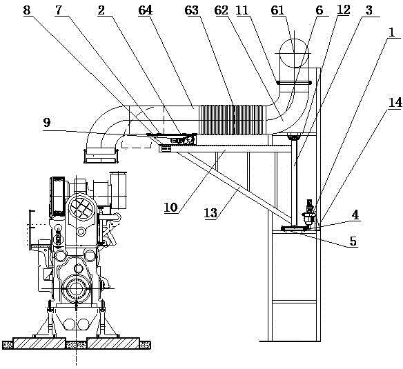
[0012] like figure 1 As shown, the engine test bench exhaust system of the present invention includes a swing reduction motor 1, a telescopic reduction motor 2 and an exhaust swing pipe 6, the swing reduction motor 1 is fixed on the bracket 14, and the swing reduction motor 1 output shaft There is a small gear 4 on the end sleeve, and the pinion gear 4 meshes with the large gear 5 in the horizontal direction. The large gear 5 is set on the swing tube shaft 3, and the swing platform 12 is installed on the top of the swing tube shaft 3. The exhaust swing tube 6 includes exhaust pipes connected in sequence. Fixed pipe 61, curved pipe section 62, telescopic hose 63 and telescopic section hard pipe 64, telescopic deceleration motor 2 is installed under telescopic section hard pipe 64, and telescopic section hard pipe 64 is equipped with linear guide...


PUM


Abstract

The invention discloses an engine test bed exhaust system comprising a swing reduction motor, a telescoping reduction motor and an exhaust swing tube. The output shaft end of the swing reduction motor is sleeved with a small gear; the small gear meshes with a large gear in the horizontal direction; the large gear sleeves a swing tube spindle; a swing platform is provided on the top of the swing tube spindle; the exhaust swing tube comprises an exhaust fixed tube, a bend segment, a telescopic hose and a telescopic segment rigid tube which are connected in sequence; the telescoping reduction motor is mounted under the telescopic segment rigid tube; a linear guide assembly is mounted on the telescopic segment rigid tube; racks are evenly distributed on the linear guide assembly; one end of the telescoping reduction motor drives a gear to rotate and mesh with the racks above; the telescoping reduction gear is fixed on a support bed-top; the swing platform supports the bend segment of the exhaust swing tube. The engine test bed exhaust system allows quick butt joint of an exhaust line and a test engine and allows smooth exhausting, test preparation time is greatly shortened, and utilization rate of a test bed is increased.

Description

technical field [0001] The invention relates to an engine test bench exhaust system. Background technique [0002] When the engine leaves the factory for bench performance tests, it is necessary to manually connect multiple pipes such as engine cooling water, fuel oil, engine oil, air intake, supercharged intercooler, and drain pipes. To realize the connection of oil, water, gas, electricity and the test engine requires a lot of The time is low, and the efficiency is low. If the engine exhaust pipe is not connected correctly, there will be air leakage, which will lead to inaccurate test results. Therefore, it is necessary to provide a new technical solution to solve the above problems. Contents of the invention [0003] In order to solve the above problems, the present invention provides a fast and efficient engine test bench exhaust system. [0004] The technical scheme adopted in the present invention is: [0005] Engine test bench exhaust system, the exhaust system i...

Claims


Application Information

Patent Timeline
Patent Type & Authority Applications(China)
IPC IPC(8): G01M15/02
Inventor 张辉赵爱国
Owner QIDONG LIANTONG DYNAMOMETER
Why Eureka
Try Eureka