Paving device for sidewalk floor tiles for road construction

A technology for laying devices and sidewalks, which is applied to roads, roads, pavements paved with prefabricated blocks, etc., and can solve problems such as time-consuming, time-consuming and labor-intensive, and disorderly brick materials

Active Publication Date: 2021-05-14
无锡鑫惠建设工程有限公司
View PDF13 Cites 0 Cited by
  • Summary
  • Abstract
  • Description
  • Claims
  • Application Information

AI Technical Summary

Problems solved by technology

[0003] However, the existing sidewalk floor tiles need to be manually laid on the ground one by one by bricks when laying. First, the bricks need to be pulled to the site with a truck, and then the bricks are manually lowered or the bricks are unloaded. The final brick materials are relatively messy and disorderly, and then the messy bricks are placed on the ground in a flat and aligned manner manually, which is time-consuming and labor-intensive. relatively long

Method used


Image

  • Paving device for sidewalk floor tiles for road construction
  • Paving device for sidewalk floor tiles for road construction
  • Paving device for sidewalk floor tiles for road construction

Examples


Embodiment 1

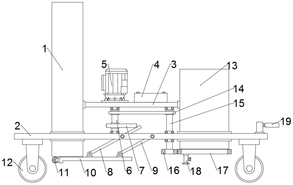
[0021] see Figure 1~3 , in an embodiment of the present invention, a sidewalk floor tile laying device for road construction, comprising a brick box 1, a car board 2 for fixing the brick box 1, moving wheels 12 installed at the four corners below the car board 2, and a Swing assembly; specifically, the brick box 1 runs through the car plate 2, the side wall of the brick box 1 is fixed with a beam 3, and the flange of the beam 3 is fixed with a drive motor 5 connected to a power supply and a switch with a wire, and the drive motor 5 outputs The end is connected to the output shaft 6, the bearing at the lower end of the output shaft 6 is connected to the car plate 2, and the switch is turned on to make the drive motor 5 energized to drive the output shaft 6 to rotate; the output shaft 6 is connected to the swing assembly;

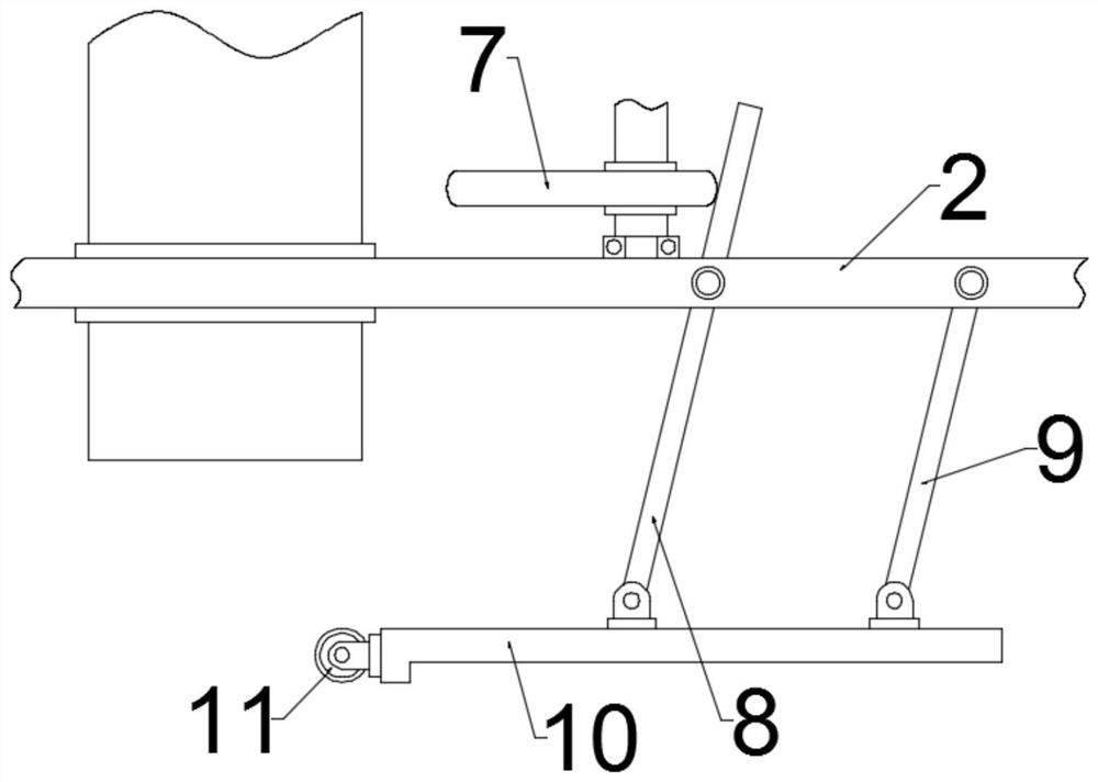
[0022] Further, the swing assembly includes a cam 7 fixed on the output shaft 6, an active lever 8 whose upper part abuts on the cam 7, a supporting plate 1...

Embodiment 2

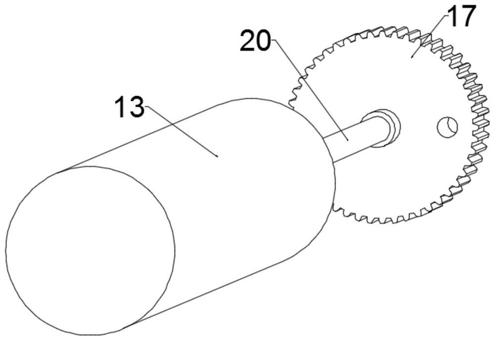
[0027] In order to further explain the above-mentioned sidewalk floor tile laying device for road construction, the present application provides another embodiment. A boom 20 is fixed at the center of the inner wall of the large gear 17, and the boom 20 is installed in the sandbox 13, and the suspension The upper end of bar 20 is rotatably connected on the cage, and the cage is fixed in the sandbox 13, and the height of bull gear 17 is fixed by cooperation of suspension rod 20 and cage.

[0028] A column is fixed above the rear portion of the vehicle plate 2, and the column is covered with a traction ring 19 connected with the traction tool. The equipment is connected to realize the movement of the device and achieve the function of moving brick laying and caulking.

[0029] According to the specific description of the above embodiment, it is easy to know that the working principle of the present invention is: turn on the switch to make the drive motor 5 energized to drive the...


PUM


Abstract

The invention discloses a sidewalk floor tile laying device for road construction, in particular to a cam-driven active rod to drive the supporting plate to swing up and down reciprocally, and under the joint action of the driven rod, the supporting plate can be horizontally swung to ensure that the bricks can be laid one by one. The unique discharge device from the lower part of the brick box solves the problem that the existing brick laying work needs to be done manually and the labor intensity is high. The brick box runs through the vehicle board, the side wall of the brick box is fixed with a beam, the flange on the beam is fixed with a wire connected to the power supply and the driving motor of the switch, the output end of the driving motor is connected to the output shaft, and the swing assembly includes a cam fixed on the output shaft, The upper part of the active rod abutting against the cam, the supporting plate hinged at the lower end of the active rod, and the driven rod connecting the vehicle plate and the supporting plate, wherein the middle part of the active rod is rotatably connected to the vehicle plate, and the lower end of the driven rod is hinged on the On the pallet, the upper end of the driven rod is hinged on the vehicle board, and the driven rod and the driving rod are in a parallel relationship.

Description

technical field [0001] The invention relates to a road laying machine, in particular to a sidewalk floor tile laying device for road construction. Background technique [0002] At present, sidewalks are provided on both sides of urban roads for pedestrians to walk on. As an important component of urban traffic, sidewalks are mostly paved with sidewalk bricks. Most of the sidewalk bricks are made of prefabricated small pieces of concrete or processed stone, and then laid on the sidewalk. [0003] However, the existing sidewalk floor tiles need to be manually laid on the ground by bricks one by one when laying. At first, the bricks need to be pulled to the site with a truck, and then the bricks are manually lowered or the bricks are unloaded. The final brick materials are relatively messy and disorderly, and then the messy bricks are placed on the ground in a flat and aligned manner manually, which is time-consuming and labor-intensive, and the labor intensity is very high, a...

Claims


Application Information

Patent Timeline
Patent Type & Authority Patents(China)
IPC IPC(8): E01C5/04E01C15/00
CPCE01C5/04E01C15/00
Inventor 刘加华
Owner 无锡鑫惠建设工程有限公司
Why Eureka
Try Eureka