
Stand-off ratio voltage coefficient detection method based on separable direct current voltage divider

A technology of DC voltage divider and voltage coefficient, which is applied in the direction of measuring current/voltage, instruments, measuring devices, etc. It can solve the problem of increasing the implementation steps of DC voltage addition test, reducing the accuracy of voltage coefficient of DC voltage dividing ratio, and complex calculation formulas, etc. problems, to achieve the effect of improving the level of measurement uncertainty, simple detection steps, and accurate detection results

Active Publication Date: 2015-02-18
STATE GRID CORP OF CHINA +2
View PDF6 Cites 7 Cited by
  • Summary
  • Abstract
  • Description
  • Claims
  • Application Information

AI Technical Summary

Problems solved by technology

This not only makes the calculation formula of the voltage coefficient of the DC voltage division ratio more complicated, but also increases the implementation steps of the DC voltage addition test
At the same time, because it is very difficult to measure the difference between the resistance value of the low-voltage arm when the auxiliary DC voltage divider is used in series and when it is used alone, it is easy to introduce additional measurement errors into the calculation results of the voltage coefficient of the DC voltage divider ratio, reducing the DC voltage divider ratio. Accuracy of Voltage Coefficient Measurements

Method used


Image

  • Stand-off ratio voltage coefficient detection method based on separable direct current voltage divider
  • Stand-off ratio voltage coefficient detection method based on separable direct current voltage divider
  • Stand-off ratio voltage coefficient detection method based on separable direct current voltage divider

Examples


Embodiment Construction

[0037] Embodiments of the present invention are described in detail below, examples of which are shown in the drawings, wherein the same or similar reference numerals designate the same or similar elements or elements having the same or similar functions throughout. The embodiments described below by referring to the figures are exemplary and are intended to explain the present invention and should not be construed as limiting the present invention.

[0038] 1. The voltage coefficient of the voltage division ratio;

[0039] The voltage division ratio of the DC voltage divider is different under different voltages, and the voltage coefficient of the voltage division ratio indicates the relative variation of the voltage division ratio under different voltages.

[0040] 2. DC voltage addition test;

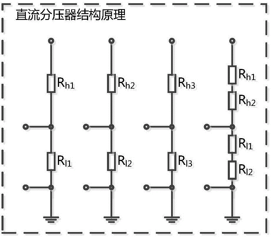
[0041] 1. The DC voltage addition test is used as the main detection method for the voltage coefficient of the voltage division ratio, and three DC voltage dividers are required:

...


PUM


Abstract

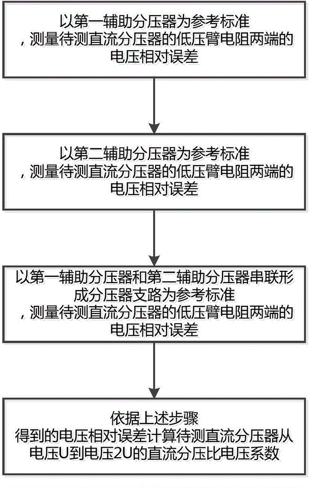
The invention provides a stand-off ratio voltage coefficient detection method based on a separable direct current voltage divider. The method comprises the steps of 1, measuring the relative error of the voltage of a low-voltage arm resistor of a direct current voltage divider to be measured with a first auxiliary voltage divider as the reference standard; 2, measuring the relative error of the voltage of the low-voltage arm resistor of the direct current voltage divider to be measured with a second auxiliary voltage divider as the reference standard; 3, measuring the relative error of the voltage of the low-voltage arm resistor of the direct current voltage divider to be measured with a voltage divider subcircuit formed by series connection of the first auxiliary voltage divider and the second auxiliary voltage divider as the reference standard; 4, calculating the stand-off ratio voltage coefficient of the direct current voltage divider to be measured. Compared with the prior art, the method has the advantages that detection is easier and more convenient, a detection result is more accurate, and the influence of the difference in low-voltage arm resistors of auxiliary voltage dividers on calculation of the stand-off ratio voltage coefficient of the direct current voltage divider to be measured existing during a direct voltage addition test is avoided.

Description

technical field [0001] The invention relates to a method for detecting the voltage coefficient of a DC voltage division ratio, in particular to a method for detecting the voltage coefficient of a voltage division ratio based on a separable DC voltage divider. Background technique [0002] DC voltage divider (DC voltage divider) is a device used in power systems and electrical and electronic equipment manufacturing departments to measure DC high voltage. The voltage divider ratio is generally traceable to the DC standard voltage divider. The traceability process of the voltage division ratio value of the DC standard voltage divider can be decomposed into the calibration of the resistance ratio at low voltage and the determination of the voltage coefficient of the voltage division ratio at high voltage. [0003] DC voltage addition is a method of calculating the voltage coefficient of the DC voltage divider ratio based on the test measurement results under the actual working v...

Claims


Application Information

Patent Timeline
IPC IPC(8): G01R19/10
Inventor 李登云章述汉胡浩亮李鹤熊前柱杨春燕刘浩
Owner STATE GRID CORP OF CHINA
Learn More