Straw returning plow

A technology of straw and hydraulic motor, which is applied in crop processing machines, cutters, agricultural machinery and implements, etc., can solve the problems of small tillering quantity, low germination rate, easy freezing to death, etc., and achieves large tillering quantity, high germination rate, simple structure

Active Publication Date: 2015-02-25
李健
View PDF6 Cites 2 Cited by
  • Summary
  • Abstract
  • Description
  • Claims
  • Application Information

AI Technical Summary

Problems solved by technology

[0002] At present, most of the plows used for plowing do not have the function of returning straw to the field. If the straw is to be returned to the field before plowing, an additional straw returning machine is required.
However, most of the corn stalks returned to the field in rural areas are crushed first and then plowed or rotary plowed. There is also a method of burying the corn stalks without crushing. No matter which method of returning corn stalks to the field, there is a shortcoming, that is, it cannot be quickly Effectively bury the stalks completely. After plowing, part of the stalks are still exposed on the surface, and more of them are exposed by rotary plowing. As a result, a considerable part of the wheat seeds are sown on the stalks during sowing, which results in post-sowing problems. The germination rate is low, the tillering amount is small, and 5-10 catties more seeds are sown per mu, and the seedlings are weak, and they are easy to freeze to death in winter
In addition, although there are straw returning machines used together with plows, the burial depth of straw is still relatively shallow, and some straw will still be exposed on the ground.

Method used


Image

  • Straw returning plow
  • Straw returning plow
  • Straw returning plow

Examples


Embodiment Construction

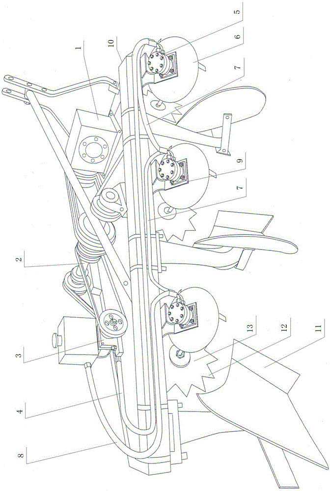
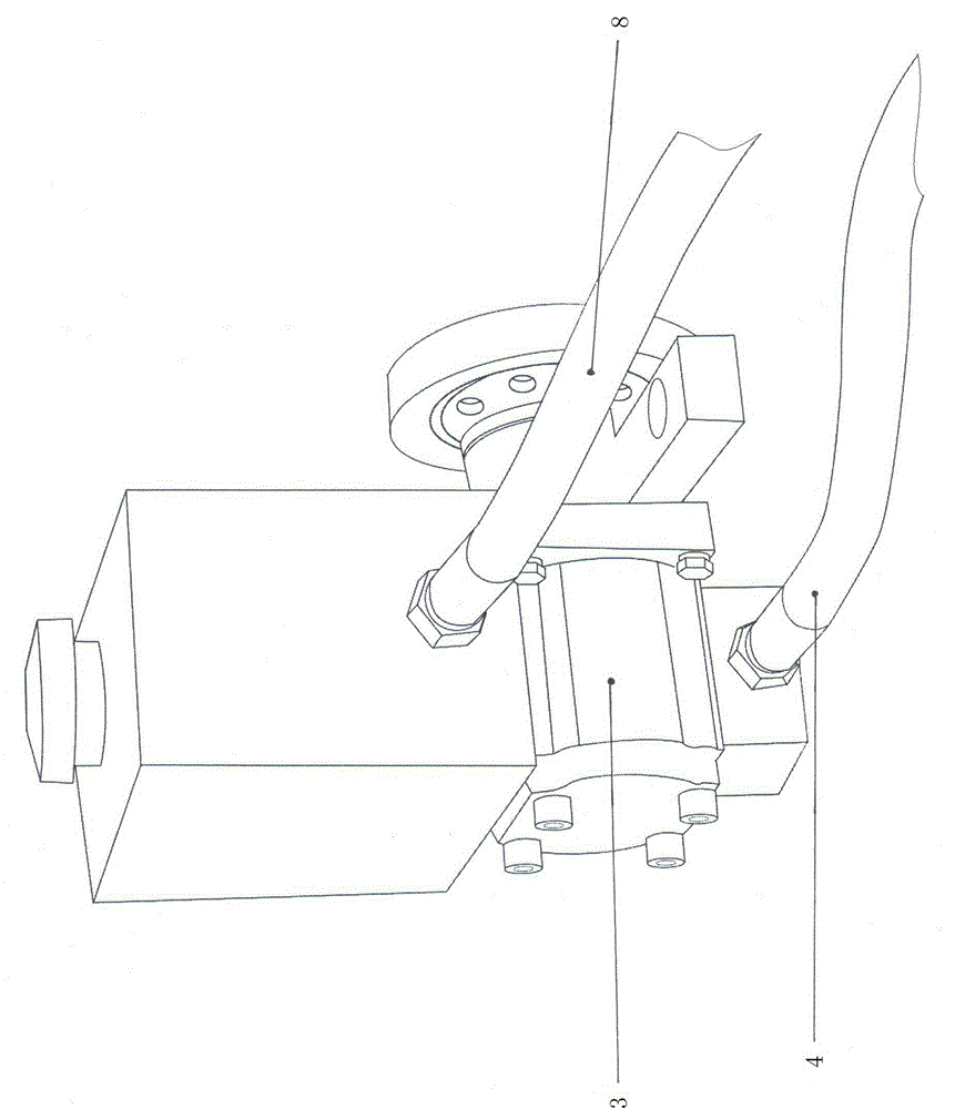
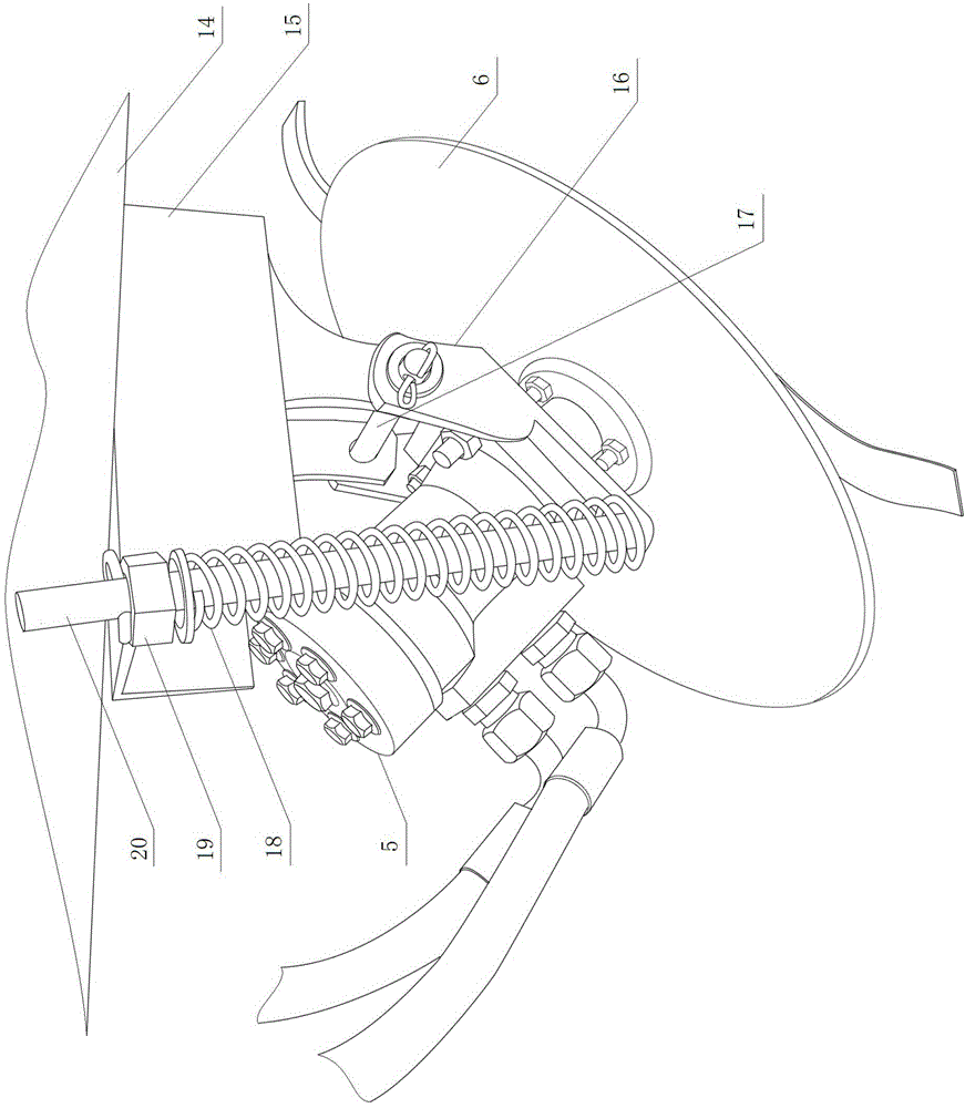
[0012] Such as Figure 1-3 As shown, a straw returning plow includes a plow 10, the plow 10 is provided with a universal joint with one end connected to the output shaft of the tractor, a gearbox transmission 1 arranged on the front beam of the plow, and a gear box transmission 1 arranged on the plow beam. The intermediate shaft 2, some wheel shafts arranged in front of each plowshare 11, and some saw wheels 13 with knife tips 12, the other end of the universal joint is connected with the input end shaft of the gearbox transmission 1, and the gearbox transmission The shaft at the output end of 1 is connected to the intermediate shaft 2 through a grooved pulley and a belt, and the plurality of saw wheels 13 are respectively installed on the plurality of wheel shafts, and the plurality of wheel shafts are all connected to the intermediate shaft 2 through a grooved wheel and a belt. It is characterized in that it also includes a hydraulic pump 3, a number of hydraulic motors 5, a...


PUM


Abstract

A straw returning plow comprises a plow body. The plow body is provided with a universal joint, a gearbox transmission, a middle shaft, a plurality of wheel shafts and a plurality of saw wheels; one end of the universal joint is connected with an output shaft of a tractor; the gearbox transmission is disposed on a front beam of the plow body; the middle shaft is disposed on a main beam of the plow body; the wheel shafts are disposed in front of plowshares; each saw wheel is provided with tips. The straw returning plow further comprises a hydraulic pump, a plurality of hydraulic motors, a plurality of straw compression discs, a high-pressure oil pipe, high-pressure series oil pipes and a return oil pipe; the hydraulic pump is disposed behind the middle shaft; an input shaft of the hydraulic pump is connected with the middle shaft through a grooved wheel and a belt; the hydraulic motors are disposed in front of the plowshares on a plurality of elastic supports which are connected with the main beam of the plow body and which can float up and down; each straw compression disc connected with an output shaft of each hydraulic motor is provided under each elastic support; each straw compression disc is provided outside each saw wheel. The straw returning plow has the advantages that each whole straw chopped or not chopped can be fully buried during plowing, burying depth is small, and the straws are never exposed.

Description

technical field [0001] The invention designs a plow, in particular a straw returning plow. Background technique [0002] At present, most of the plows used for plowing do not have the function of returning straw to the field. If the straw is to be returned to the field before plowing, it is necessary to add a straw returning machine. However, most of the corn stalks returned to the field in rural areas are crushed first and then plowed or rotary plowed. There is also a method of burying the corn stalks without crushing. No matter which method of returning corn stalks to the field, there is a shortcoming, that is, it cannot be quickly Effectively bury the stalks completely. After plowing, part of the stalks are still exposed on the surface, and more of them are exposed by rotary plowing. As a result, a considerable part of the wheat seeds are sown on the stalks during sowing, which results in post-sowing problems. The germination rate is low, the amount of tillers is small, an...

Claims


Application Information

Patent Timeline
Patent Type & Authority Applications(China)
IPC IPC(8): A01D82/00
Inventor 李健
Owner 李健
Why Eureka
Try Eureka