A horizontal punching tool for pipe fittings

A technology for horizontal punching and pipe fittings, which is used in punching tools, manufacturing tools, metal processing equipment, etc. It can solve the problem of horizontal punching tooling without handrails, and achieve the effect of compact structure, high punching accuracy and long stroke.

Active Publication Date: 2016-08-24
NANTONG JIANGHUA MASCH CO LTD
View PDF6 Cites 0 Cited by
  • Summary
  • Abstract
  • Description
  • Claims
  • Application Information

AI Technical Summary

Problems solved by technology

[0003] The handrail of the lawn mower is U-shaped during the processing process, and it is necessary to perform horizontal punching on both sides and the middle part of the U-shaped pipe fitting. At present, there is no horizontal punching tool for the handrail. Horizontal punching tool for pipe fittings with simultaneous horizontal punching in the middle

Method used


Image

  • A horizontal punching tool for pipe fittings
  • A horizontal punching tool for pipe fittings
  • A horizontal punching tool for pipe fittings

Examples


Embodiment Construction

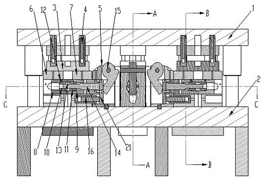
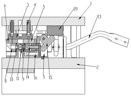
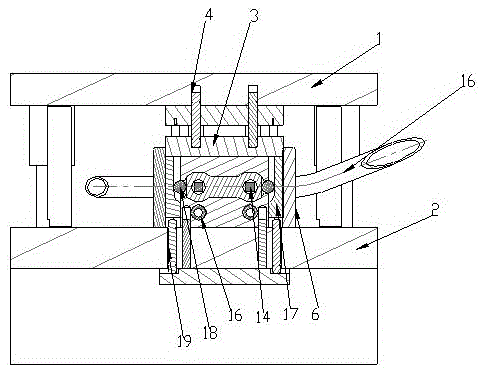
[0024] Such as figure 1 , figure 2 , image 3 and Figure 4 As shown, the present invention discloses a horizontal punching tool for pipe fittings, including an upper template 1, a lower template 2, and a guide post guide sleeve structure arranged between the upper template 1 and the lower template 2, the upper template 1 and the lower template 2 Several horizontal punching stations are set between them,

[0025] The lower end surface of the upper template 1 of each horizontal punching station is provided with an upper movable platen 3, and a buffer cylinder 4 is arranged between the upper movable platen 3 and the upper template 1; Strike block mounting seat 5, left die seat 6 and right die seat 7;

[0026] A groove A supporting the pipe fitting 13 is formed in the middle between the left die base 6 and the right die base 7, and the left movable block 8 and the right movable block 9 are respectively arranged in the left die base 6 and the right die base 7. Left movable b...


PUM


Abstract

The invention relates to a pipe horizontal punching tool which comprises an upper die plate, a lower die plate and a guide pillar and guide sleeve structure arranged between the upper die plate and the lower die plate. The pipe horizontal punching tool is characterized in that a plurality of horizontal punching stations are arranged between the upper die plate and the lower die plate, an upper movable pressing plate is arranged on the lower end face of the upper die plate of each horizontal punching station, and a cushioning cylinder is arranged between each upper movable pressing plate and the upper die plate; correspondingly, the lower die plate is provided with collision block mounting seats which are arranged adjacently, left concave die seats and right concave die seats; grooves A used for supporting pipes are formed between the left concave die seats and the right concave die seats, and left movable blocks, right movable blocks, left movable concave dies and right movable concave dies are arranged in the left concave die seats and the right concave die seats, wherein the left movable concave dies and the right movable concave dies are embedded in the inner walls of the left movable blocks and the inner walls of the right movable blocks respectively; through holes used for punching are formed in the left movable concave dies and the right movable concave dies, and arc-shaped grooves B used for clamping the pipes are arranged in the die assembly ends of the left movable concave dies and the right movable concave dies. The pipe horizontal punching tool has the advantages that a plurality of parts of the pipes are horizontally punched simultaneously, the punching precision is high, and the efficiency of horizontal punching of the pipes is improved.

Description

technical field [0001] The invention belongs to the field of agricultural machinery, in particular to a horizontal punching tool for pipe fittings. Background technique [0002] Lawn mower (Lawn mower) is also known as weeder, lawnmower, lawn trimmer, etc. A lawn mower is a mechanical tool for mowing lawns, vegetation, etc. It is composed of a cutter head, an engine, a walking wheel, a walking mechanism, a blade, a handrail, and a control part. The cutterhead is installed on the walking wheel, the cutterhead is equipped with an engine, and the output shaft of the engine is equipped with a blade. The blade uses the high-speed rotation of the engine to increase the speed a lot, which saves the working time of the weeding workers and reduces a lot of human resources. [0003] The handrail of the lawn mower is U-shaped during the processing process, and it is necessary to perform horizontal punching on both sides and the middle part of the U-shaped pipe fitting. At present, the...

Claims


Application Information

Patent Timeline
Patent Type & Authority Patents(China)
IPC IPC(8): B21D28/28B21D28/34
CPCB21D28/28B21D28/34
Inventor 严小惠曹锋陆琼晔蔡建刚张晓磊林欣平
Owner NANTONG JIANGHUA MASCH CO LTD
Why Eureka
Try Eureka