A liftable rail cutting device

A cutting device and rail technology, which is applied to sawing machine devices, metal sawing equipment, metal processing equipment, etc., can solve the problems of unstable walking, troublesome operation, inability to meet the needs of production, etc., so as to improve the cutting quality and ensure the levelness. , the effect of convenient operation

Active Publication Date: 2016-08-17
ZHEJIANG DESHENG RAILWAY EQUIP
View PDF6 Cites 0 Cited by
  • Summary
  • Abstract
  • Description
  • Claims
  • Application Information

AI Technical Summary

Problems solved by technology

[0002] The cross section of the modern rail is I-shaped, which is divided into the rail head in contact with the wheel, the middle rail waist and the bottom rail. Different routes have different requirements for the strength, stability and wear resistance of the rail. In the process of processing, it is necessary to use a cutting device to cut various parts of the rail, so that the rail can be cut and processed according to different needs. In the existing mechanical processing process, the common methods of plate cutting are manual cutting and mechanical cutting, manual cutting It increases the labor intensity of the workers and reduces the cutting efficiency of the rails. In the process of cutting the rails, it is necessary to ensure the accuracy of the cutting. Due to the arbitrariness of the manual operation, the quality of the rail cutting cannot be ensured efficiently. Therefore, mechanical cutting is generally used. , due to the large volume and heavy weight of the rails, in the process of cutting the rails, the existing rail placement brackets often cause unstable walking, easy deflection, and jamming during the translation process, resulting in uneven and neat rails. be cut, and the existing cutting mechanism has a complex structure and troublesome operation, and the cutting mechanism cannot be easily lifted and lowered according to the needs of rail processing, which reduces the scope of application of the rail cutting device and cannot meet the needs of production

Method used


Image

  • A liftable rail cutting device
  • A liftable rail cutting device
  • A liftable rail cutting device

Examples


Embodiment Construction

[0013] In order to further describe the present invention, a specific implementation of a liftable rail cutting device will be further described below in conjunction with the accompanying drawings. The following examples are explanations of the present invention and the present invention is not limited to the following examples.

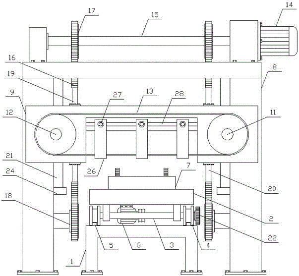
[0014] Such as figure 1 As shown, a liftable rail cutting device of the present invention includes a rail placement mechanism and a rail cutting mechanism, and the rail placement mechanism is horizontally arranged on the lower side of the rail cutting mechanism. The rail placement mechanism of the present invention includes a base 1 and a placement bracket 2, the placement bracket 2 is horizontally arranged on the upper side of the base 1, and the lower side of the placement bracket 2 is horizontally connected to a plurality of translation shafts 3, and the two ends of the translation shaft 3 are vertically and symmetrically arranged. The guide rolle...


PUM


Abstract

The invention discloses a rail cutting device capable of ascending and descending and belongs to the field of machining equipment. The rail cutting device capable of ascending and descending comprises a rail holding mechanism and a rail cutting mechanism. The rail holding mechanism is horizontally arranged on the lower side the rail cutting mechanism. The rail holding mechanism comprises a base and a holding support. The holding support is horizontally arranged on the upper side the base. The rail cutting mechanism comprises a cutting support and a cutting machine box. The cutting machine box is horizontally arranged on the cutting support. A lifting mechanism is vertically arranged between the cutting machine box and the cutting support. A cutting motor is horizontally arranged on one side of the cutting machine box. Cutting blades are arranged on a main cutting blade wheel and an auxiliary cutting blade wheel. Lifting guide rails are vertically and symmetrically arranged on the two sides of the cutting support. Lifting grooves matched with the lifting guide rails are vertically formed in the two sides of the cutting machine box. The rail cutting device capable of ascending and descending is simple in structure and capable of cutting rails accurately, rapidly and effectively according to needs, improves machining efficiency of the rails and meets production needs.

Description

technical field [0001] The invention relates to a cutting device, in particular to a lifting rail cutting device, which belongs to the field of mechanical processing equipment. Background technique [0002] The cross section of the modern rail is I-shaped, which is divided into the rail head in contact with the wheel, the middle rail waist and the bottom rail. Different routes have different requirements for the strength, stability and wear resistance of the rail. In the process of processing, it is necessary to use a cutting device to cut various parts of the rail, so that the rail can be cut and processed according to different needs. In the existing mechanical processing process, the common methods of plate cutting are manual cutting and mechanical cutting, manual cutting It increases the labor intensity of the workers and reduces the cutting efficiency of the rails. In the process of cutting the rails, it is necessary to ensure the accuracy of the cutting. Due to the arb...

Claims


Application Information

Patent Timeline
Patent Type & Authority Patents(China)
IPC IPC(8): B23D53/04B23D55/04B23D55/08
Inventor 关铁
Owner ZHEJIANG DESHENG RAILWAY EQUIP
Why Eureka
Try Eureka