Screwing machine

一种锁螺丝机、螺丝的技术,应用在螺丝刀、金属加工、板钳等方向,能够解决机台主体无法共用、成本增加、不方便等问题

Active Publication Date: 2015-02-25
QUANTA COMPUTER INC
View PDF6 Cites 8 Cited by
  • Summary
  • Abstract
  • Description
  • Claims
  • Application Information

AI Technical Summary

Problems solved by technology

[0005] At present, the screw locking machine on the market, when the production line uses the air blowing or air suction operation, the main body of the machine cannot be shared
Air-suction machines can only do air-suction operations, and air-blown machines can only do air-blown operations. If you want to change the locking mode on the production line, that is, from air-suction to air-blown Type or from the air blowing type to the air suction type, the main body of the machine must be replaced as a whole, which will increase the cost and be very inconvenient

Method used


Image

  • Screwing machine
  • Screwing machine
  • Screwing machine

Examples


Embodiment Construction

[0055] A number of implementations of the present invention will be disclosed below with the accompanying drawings. For the sake of clarity, many practical details will be described together in the following description. It should be understood, however, that these practical details should not be used to limit the invention. That is, in some embodiments of the present invention, these practical details are unnecessary. In addition, for the sake of simplifying the drawings, some conventional structures and elements will be shown in a simple and schematic way in the drawings.

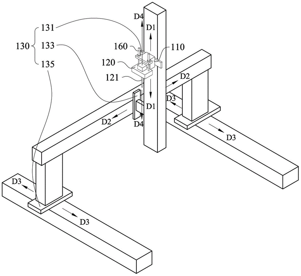
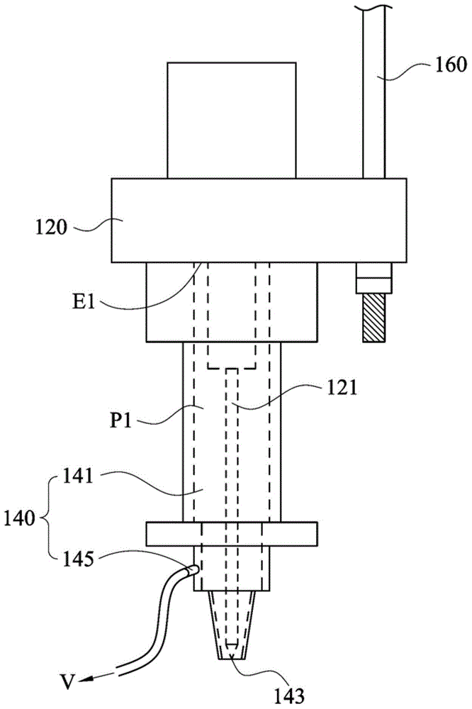
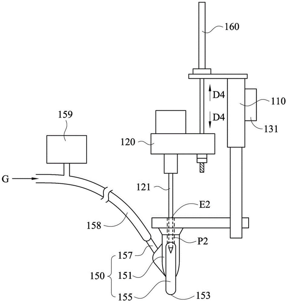
[0056] figure 1 A perspective view of the screw locking machine 100 before the air suction jig 140 or the air blow jig 150 is installed according to an embodiment of the present invention is shown. figure 2 draw figure 1 The schematic diagram of the screw locking machine 100 connected with the air suction jig 140 . image 3 draw figure 1The schematic diagram of the screw locking machine 100 connecte...


PUM


Abstract

A screwing machine includes a machine frame, a locking device, a first moving mechanism, a suction jig, a blowing jig and a second moving mechanism. The locking device has a screwdriver. The first moving mechanism moves the machine frame. The suction jig has a suction head. The blowing jig has a target head. The suction jig and the blowing jig are alternatively mounted on the screwing machine. The suction jig is mounted on the screwing machine by connecting to the locking device. The suction jig sucks to attract at least one screw to the suction head. The blowing jig is mounted on the screwing machine by connecting to the machine frame. The blowing jig blows to supply the screw to the target head. The second moving mechanism connects the locking device to the machine frame for moving the locking device relative to the machine frame.

Description

technical field [0001] The invention relates to a screw locking machine. Background technique [0002] At present, the relevant automatic and semi-automatic screw locking machines on the market are divided into two types: air suction and air blowing. The description is as follows: [0003] The air-suction locking screw machine mainly uses the vacuum suction method to suck the screws from the feeder, and then lock the screws. The operation process is such a series of processes of sucking screws and locking them. The part of the screwdriver head is covered in the suction nozzle. [0004] The air blowing screw locking machine locks the screws by air blowing. The locking process of the air-blow type is that the screw is placed in the vibrating plate, and the screw is sent to the chuck by air blowing. When the screw is delivered to the chuck, the chuck is closed at this time, and the screw is located in the chuck. When the screw After reaching the locking position, when the s...

Claims


Application Information

Patent Timeline
Patent Type & Authority Applications(China)
IPC IPC(8): B23P19/06
CPCB25B23/04B23P19/001B23P19/005B23P19/06
Inventor 郭信宏朱龙江戴栋乾
Owner QUANTA COMPUTER INC
Why Eureka
Try Eureka