Fastening device for card

a technology for fastening devices and cards, applied in the direction of coupling device connections, instruments, engagement/disengagement of coupling parts, etc., can solve the problems of complicated components, difficult installation, fastening devices, etc., and achieve the effect of simple installation procedure and easy connection

Inactive Publication Date: 2005-11-17
LIU CHIN CHING
View PDF1 Cites 12 Cited by
  • Summary
  • Abstract
  • Description
  • Claims
  • Application Information

AI Technical Summary

Benefits of technology

[0005] It is an object of the present invention to provide a device for fasteni...

Problems solved by technology

Unfortunately, such fastening devices suffered from several disa...

Method used


Image

  • Fastening device for card
  • Fastening device for card
  • Fastening device for card

Examples


Embodiment Construction

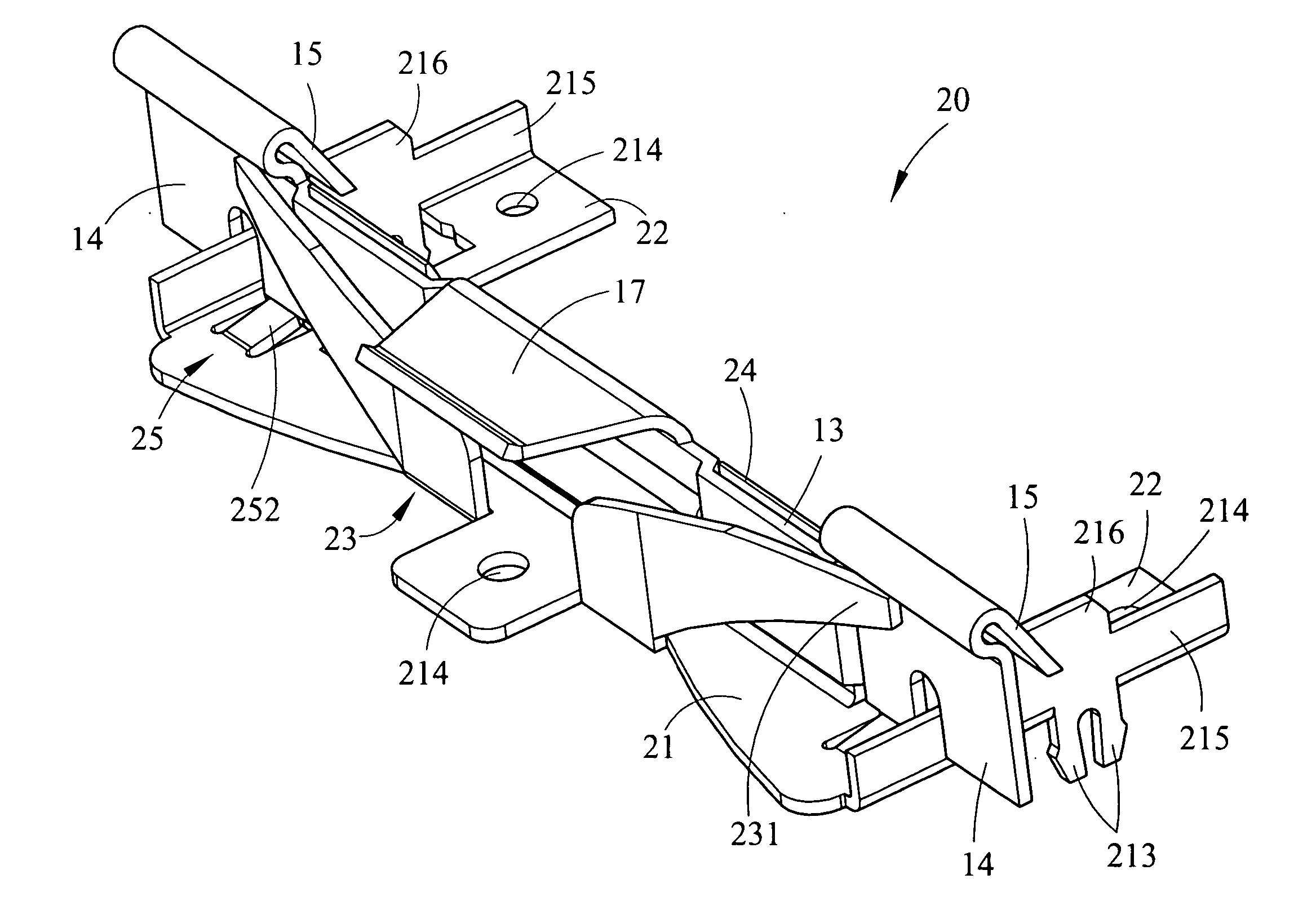
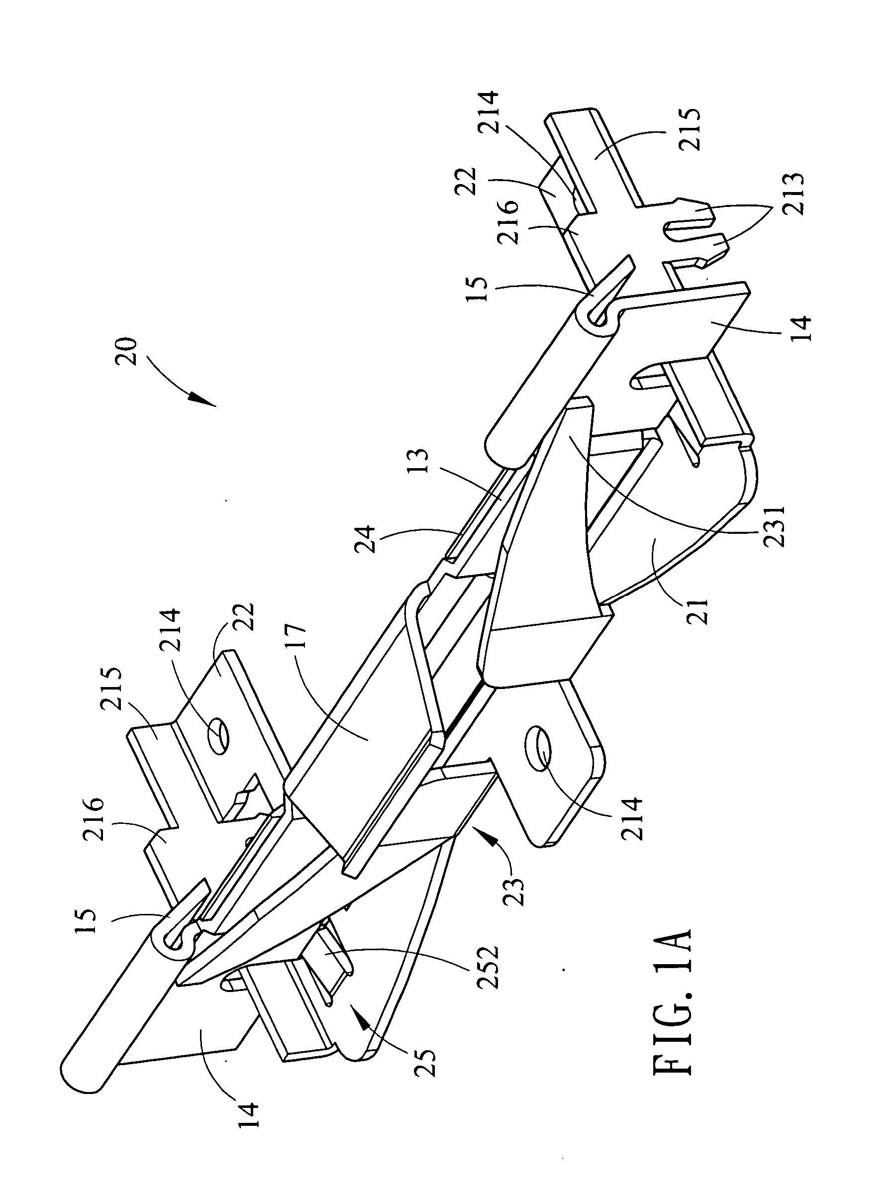
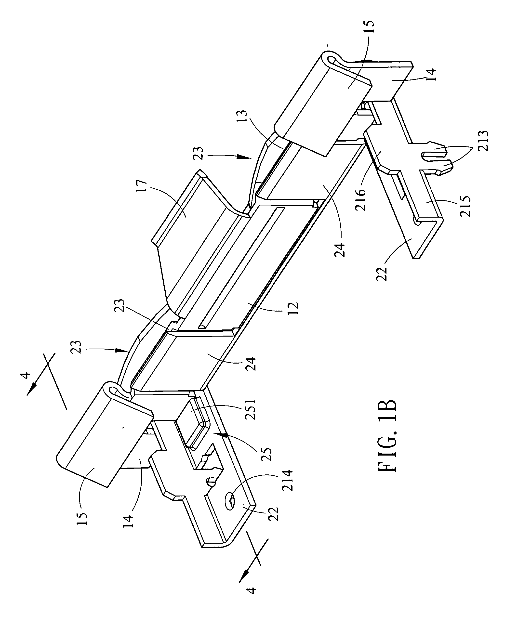
[0016] Referring to FIGS. 1A, 1B and 5, a fastening device constructed in accordance with a first preferred embodiment of the invention is shown. The fastening device is fastened on a motherboard 30 of a computer and is spaced from a connector 31. A card 40 has a first end 41 fastened at the connector 31. The fastening device comprises a snapping assembly 11 and a seat assembly 20 as described in detail below.

[0017] Referring to FIGS. 2A and 2B, the elongated, upright snapping assembly 11 comprises a thin plate 12, two wing plates 13 extended from both ends of the plate 12, two supports 14 each extended from one end of the wing plate 13, two latch elements 15 each formed on a top of the support 14, two tabs 16 each extended from a bottom of the support 14 and being perpendicular thereto, and a latch member 17 arcuately extended from a top of the plate 12. The extending direction of the latch element 15 is opposite to that of the latch member 17. A force exerted upon the latch eleme...


PUM


Abstract

A device for fastening a card on the motherboard of a computer is provided. In one embodiment, the device comprises an elongated, upright snapping assembly and a substantially U-shaped seat assembly secured thereon. Fastening a first end of the card at a connector on the motherboard, placing the second end thereof in the fastening device by pressing a latch member, positioning two risers in two slits of the second end, and releasing the latch member will cause two latch elements to exert a resilient force on the second end of the card for fastening.

Description

BACKGROUND OF THE INVENTION [0001] 1. Field of the Invention [0002] The present invention relates to fastening devices and more particularly to an improved device for fastening a card on the motherboard of a computer. [0003] 2. Description of Related Art [0004] Conventionally, a card is added to a computer for providing additional functions. The size of card is reduced gradually as the development of miniature electronic products. For example, a card is disposed laterally in a notebook complying with mini PCI (Peripheral Component Interconnect). That is, holes of the connector on the motherboard are disposed laterally. A card is thus disposed laterally on the motherboard after fastening at the connector. As an end, the occupied height is much reduced. Also, fastening devices are provided on the motherboard for holding the card stably in addition to the snapping coupling force of the connector exerted on the card. Unfortunately, such fastening devices suffered from several disadvanta...

Claims


Application Information

Patent Timeline
IPC IPC(8): G06F1/16H01R12/00H01R13/62H05K7/14
CPCH05K7/1405H01R12/721H01R12/7029
Inventor LIU, CHIN-CHING
Owner LIU CHIN CHING
Why Eureka
Try Eureka