Building form board perforating device

A technology of punching device and building template, applied in positioning device, feeding device, boring/drilling and other directions, can solve the problems of complicated operation steps, reduce the efficiency of punching, low work efficiency, etc., to simplify the installation procedure, Easy maintenance and strong practicability

Inactive Publication Date: 2019-07-19
固始晶鑫木业有限公司
View PDF6 Cites 12 Cited by
  • Summary
  • Abstract
  • Description
  • Claims
  • Application Information

AI Technical Summary

Problems solved by technology

[0002] At present, building templates are widely used in building houses, decorating indoor environments, and making indoor furniture because of their strength and easy processing and installation. Hole operation, the traditional punching method is to punch holes with a hand-held punching machine. Although it is easy to carry and easy to operate, it has defects such as high labor intensity and low work efficiency. In addition, manual punching is easy to cause deviations. , the stability and accuracy are relatively poor. The existing automatic punching device has cumbersome operation steps in the process of punching the building formwork, which affects the punching process and reduces the efficiency of punching. It cannot meet the needs of modern production and use.
[0003] In view of the above problems, the existing patent notification number is CN108481426B, which provides a template punching device. This device adjusts the punching point by adjusting the position of the drill bit relative to the template, but the device will adjust the drill bit circumferential rotation and level. The rotating structure is arranged crosswise, which reduces the flexibility of the drill bit. Although this drill bit can adjust the drilling position, it cannot complete the processing of inclined holes.

Method used


Image

  • Building form board perforating device
  • Building form board perforating device
  • Building form board perforating device

Examples


Embodiment Construction

[0022] The following will clearly and completely describe the technical solutions in the embodiments of the present invention with reference to the accompanying drawings in the embodiments of the present invention. Obviously, the described embodiments are only some, not all, embodiments of the present invention. Based on the embodiments of the present invention, all other embodiments obtained by persons of ordinary skill in the art without making creative efforts belong to the protection scope of the present invention.

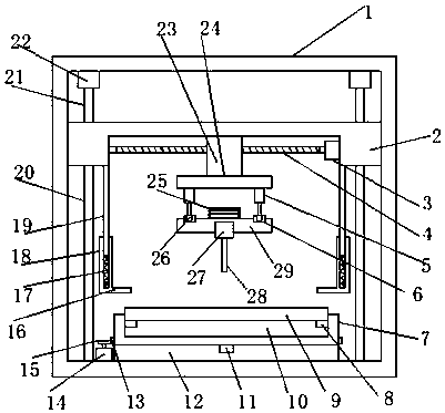
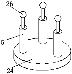
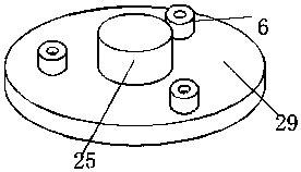
[0023] see Figure 1~3 , in an embodiment of the present invention, a building template punching device includes a frame body 1, a lifting plate 2 is slid in a rectangular cavity inside the frame body 1, and a lifting plate 2 is provided between the lifting plate 2 and the frame body 1. Lifting drive mechanism, the lifting drive mechanism is used to drive the lifting plate 2 to slide up and down along the inner wall of the frame body 1, and the lower end surfa...


PUM


Abstract

The invention discloses a building form board perforating device. The building form board perforating device comprises a frame body. An ascending-and-descending plate is arranged in a rectangular cavity inside the frame body in a sliding manner. An ascending-and-descending driving mechanism is arranged between the ascending-and-descending plate and the frame body and used for driving the ascending-and-descending plate to slide vertically along the inner wall of the frame body. A sliding base block and a horizontal sliding mechanism are arranged on the lower end face of the ascending-and-descending plate in a sliding manner, wherein the horizontal sliding mechanism drives the sliding base block to linearly slide leftwards and rightwards. A drilling platform is arranged below the sliding base block. A drilling motor is arranged at the lower end of the drilling platform. According to the building form board perforating device, improvement is conducted to overcome defects of an existing device; horizontal locating of a drill bit in the original device is separated into horizontal linear motion of a drill bit and rotation of a to-be-machined form board; the separation mode facilitates later-stage maintenance, and the mounting procedure is simplified; in addition, formation of an inclined drill hole is underlaid; and furthermore, an adjustment mechanism used for adjusting the inclination angel of the drill bit is arranged, and thus, adjustment of the inclination angel of the drill bit is completed; and the practicability is high.

Description

technical field [0001] The invention relates to the technical field of construction equipment, in particular to a construction formwork punching device. Background technique [0002] At present, building templates are widely used in building houses, decorating indoor environments, and making indoor furniture because of their strength and easy processing and installation. Hole operation, the traditional punching method is to punch holes with a hand-held punching machine. Although it is easy to carry and easy to operate, it has defects such as high labor intensity and low work efficiency. In addition, manual punching is easy to cause deviations. , stability and accuracy are relatively poor, and the existing automatic punching device has cumbersome operation steps in the process of punching building formwork, which affects the punching process, reduces the efficiency of punching, and cannot meet the needs of modern production and use. [0003] In view of the above problems, th...

Claims


Application Information

Patent Timeline
Patent Type & Authority Applications(China)
IPC IPC(8): B23B41/00B23B47/20B23Q1/26B23Q3/06
CPCB23B41/00B23Q1/26B23Q3/062B23Q5/34
Inventor 李玲玉李明喜郑伟李锐锋
Owner 固始晶鑫木业有限公司
Why Eureka
Try Eureka